My Journeymans Piece: A step by step build


One of the last things I had to do to complete my apprenticeship as a blacksmith in Germany was to build a final piece that shows what I've learned in the previous three and a half years. For this project, I didn't just want to pass the test. I wanted to push myself to design and build the best piece that I possibly could at the time. This is the story of how I completed the project and reached my desired goal.
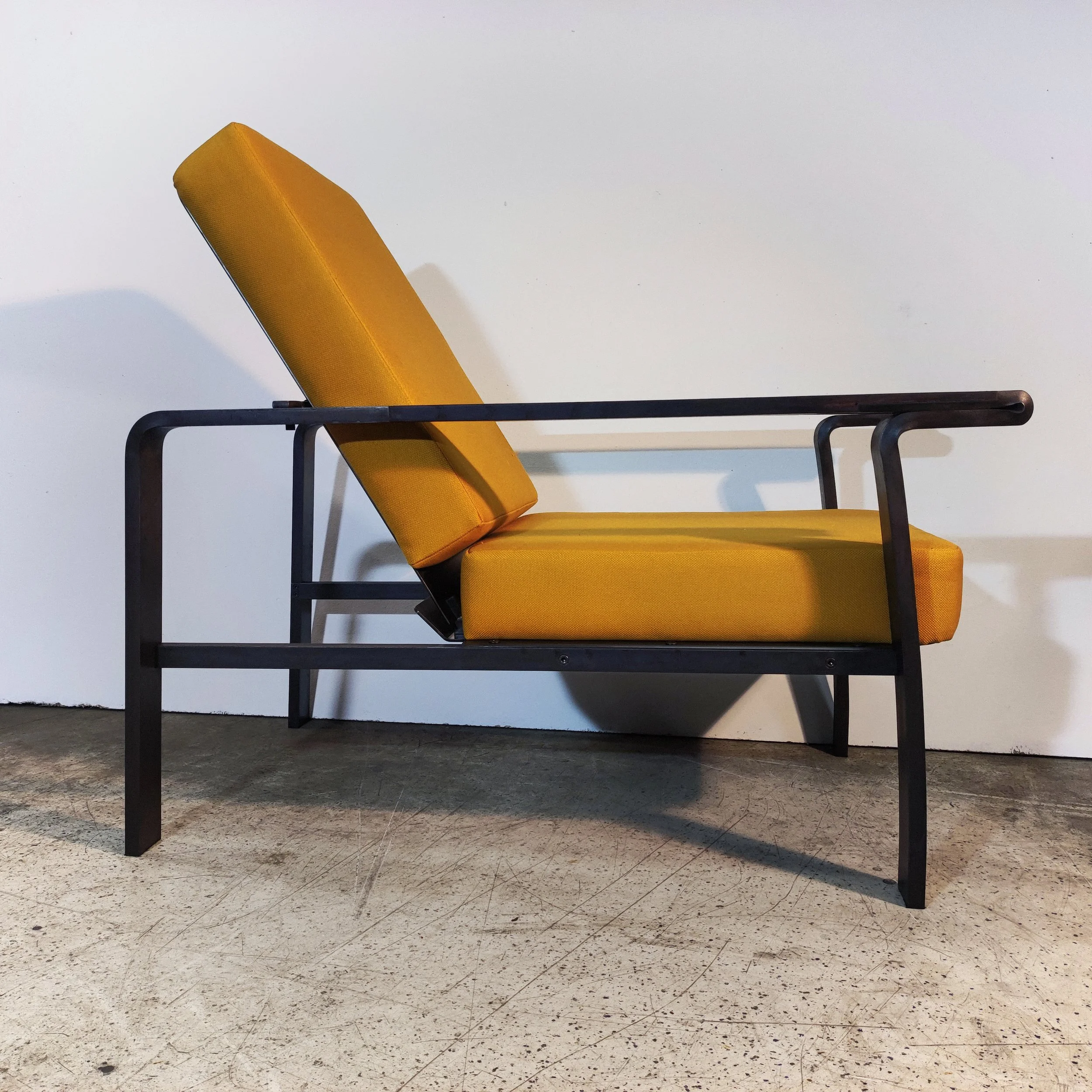
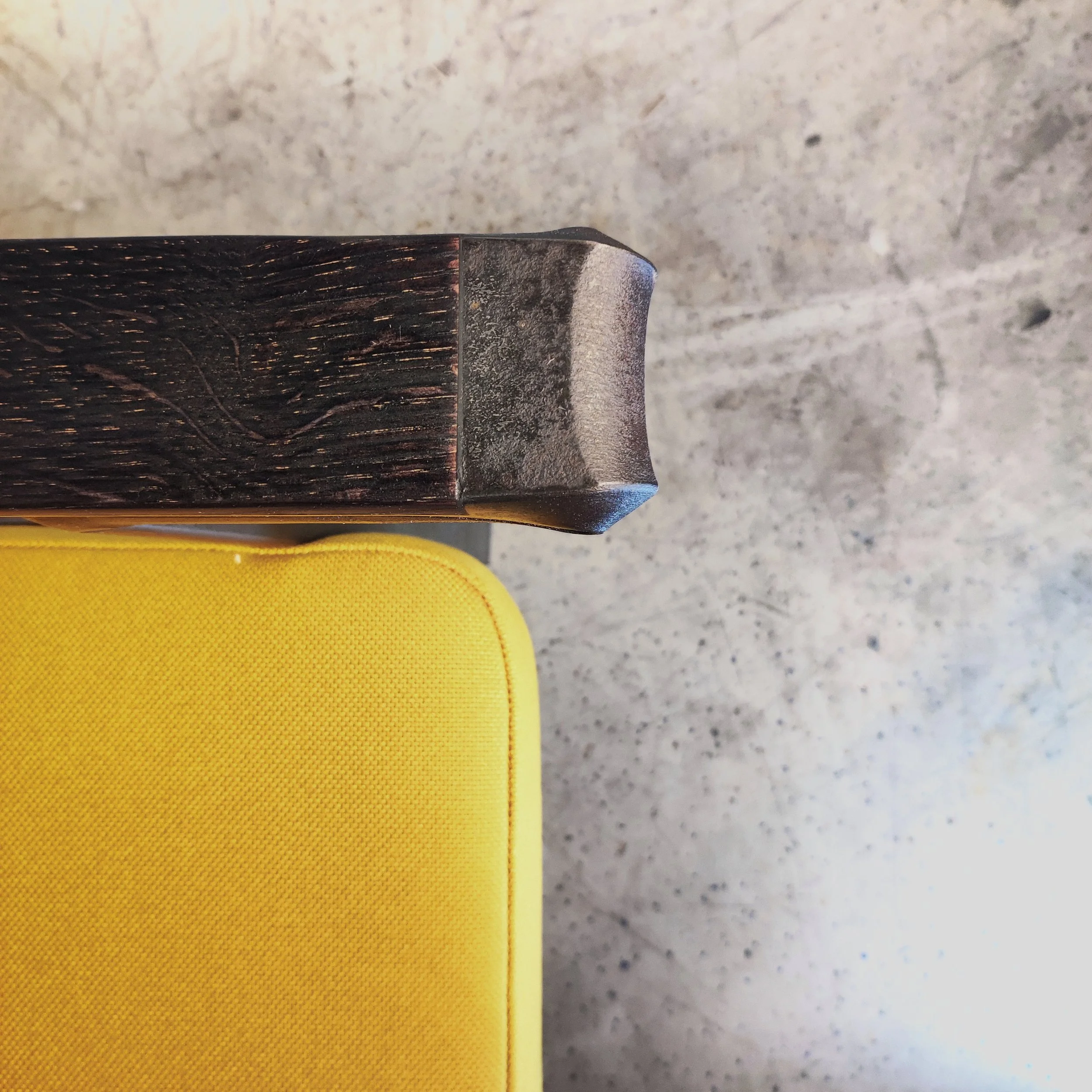
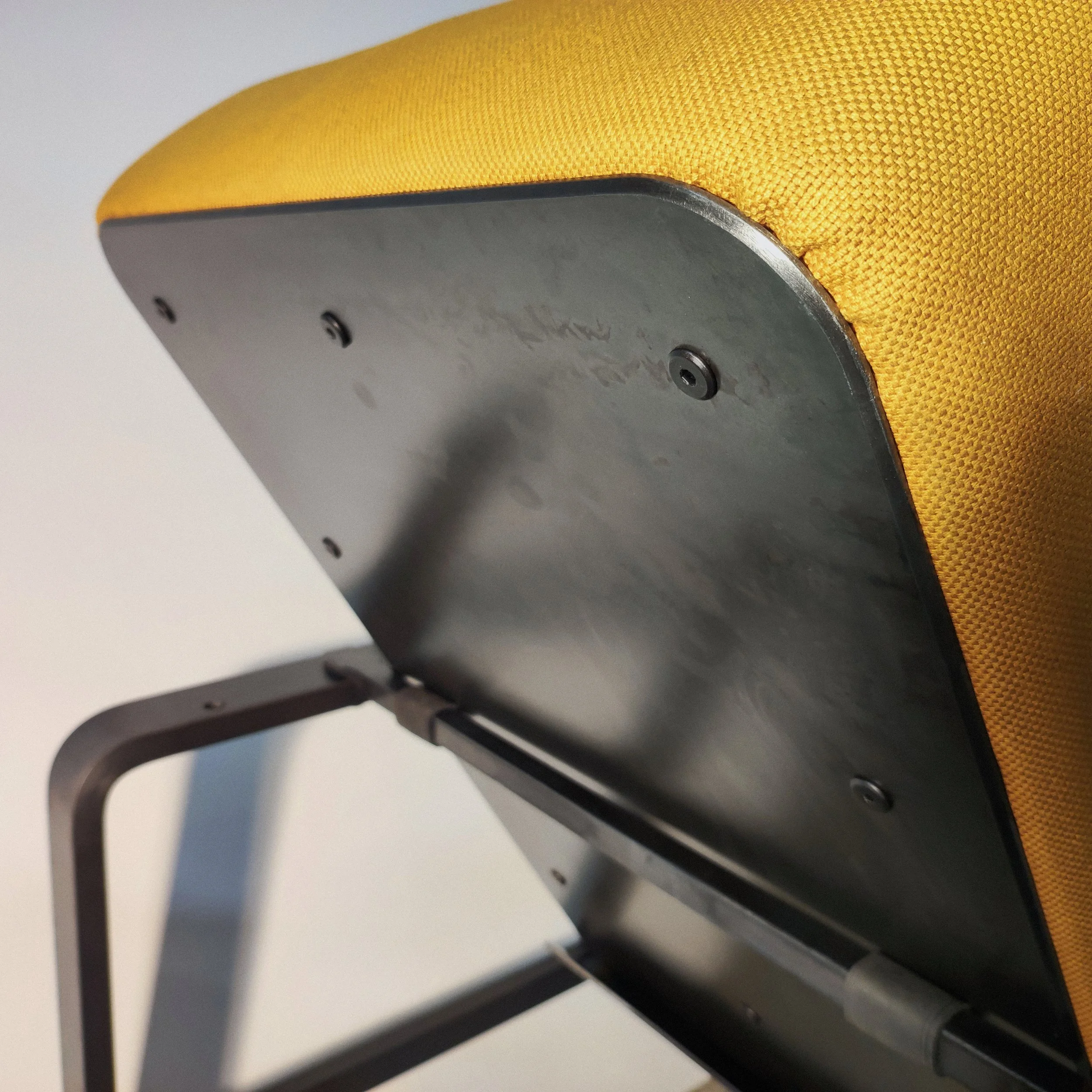
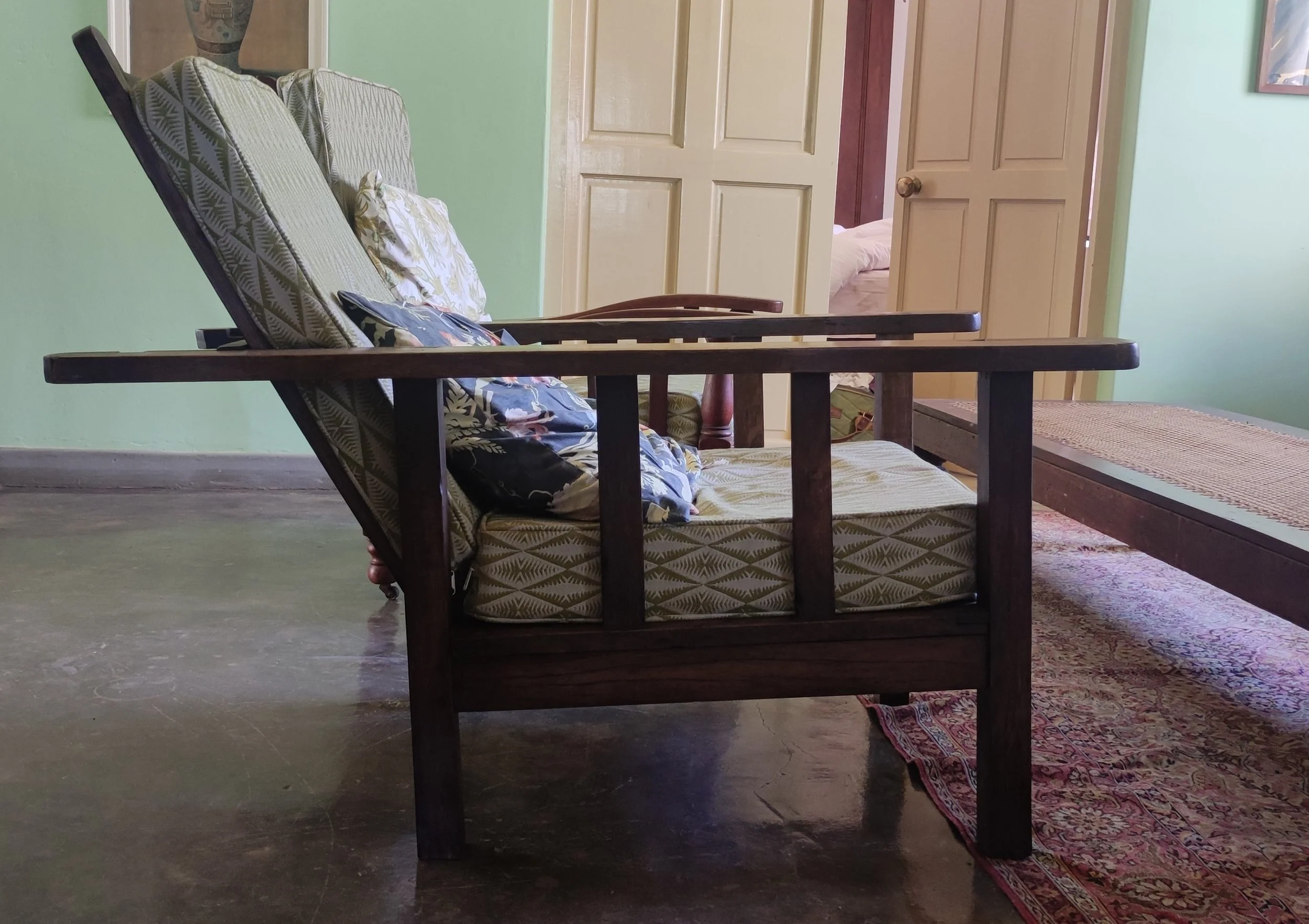
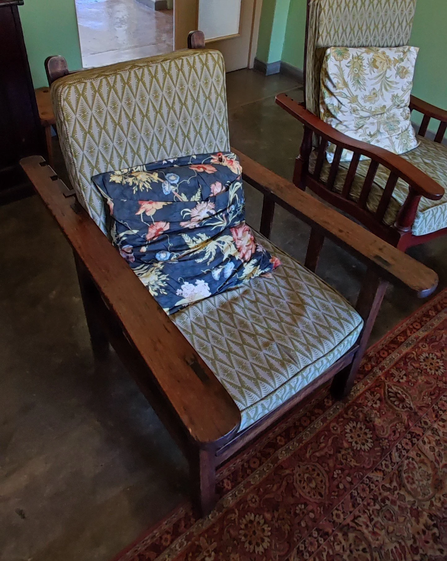
While on christmass holiday in South Africa in 2021 to visit my parents and friends, I went to a farm where I saw a beautiful, antique wooden reclining chair. It was exceptional because it had a backrest that allowed you to adjust the seating angle, depending on your current need. It had a very simple design, and the part that I liked the most was the way the angle adjustment was done. You had to move a little wooden bar into one of three possible slots on the parallel armrests. This wooden bar is what the backrest leans against, which makes the angle of the backrest change when you move the bar. See the pictures below of the chair.

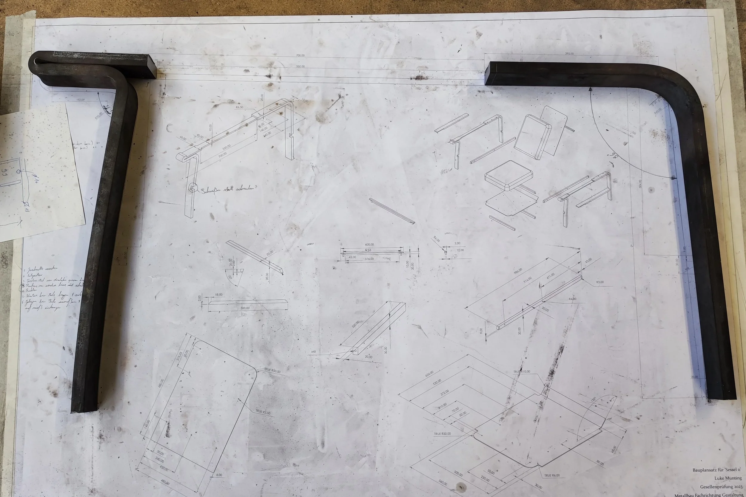
This beautiful design caught my attention and inspired me to design my own version of it in steel. I wanted to build a reclining chair with a similar mechanism to adjust the angle, without simply copying it. After a bunch of sketching and pondering, I came up with a design that I felt would be possible to build in one week by myself and that I could be proud of at the end. I drew up my design in 3D on SolidWorks and printed out technical drawings for myself to work from.
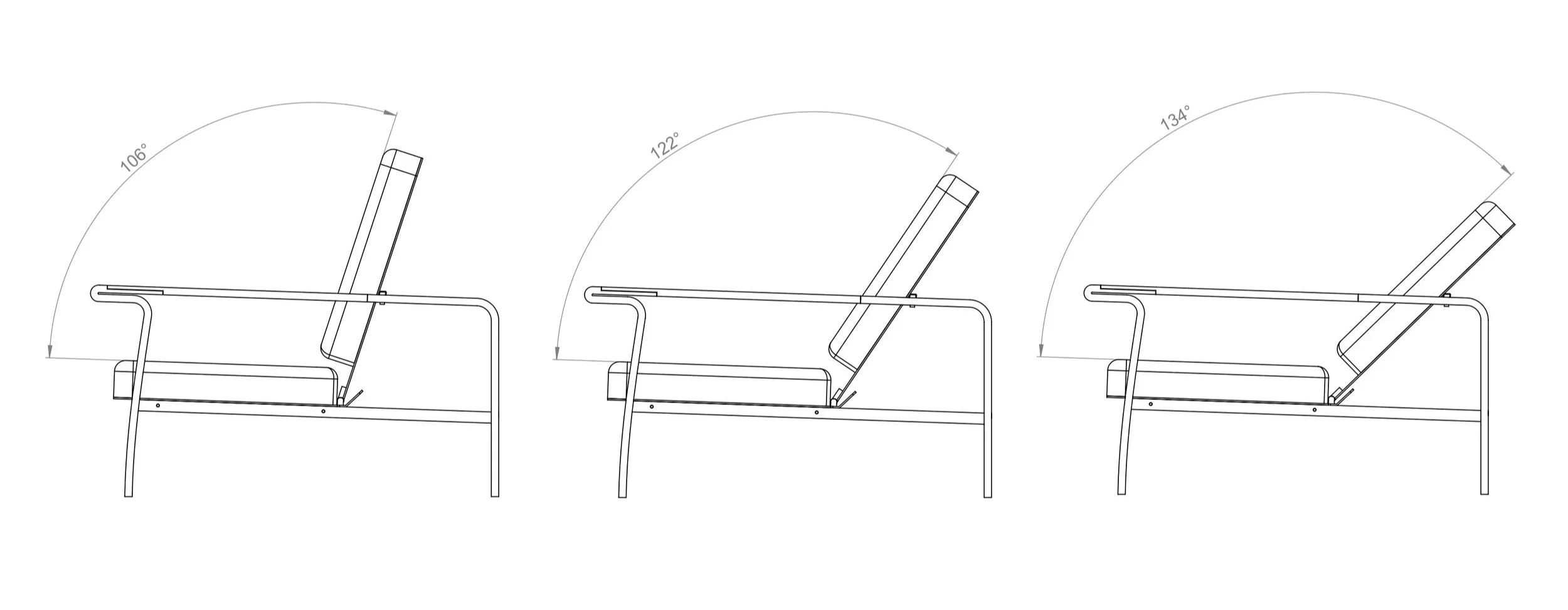
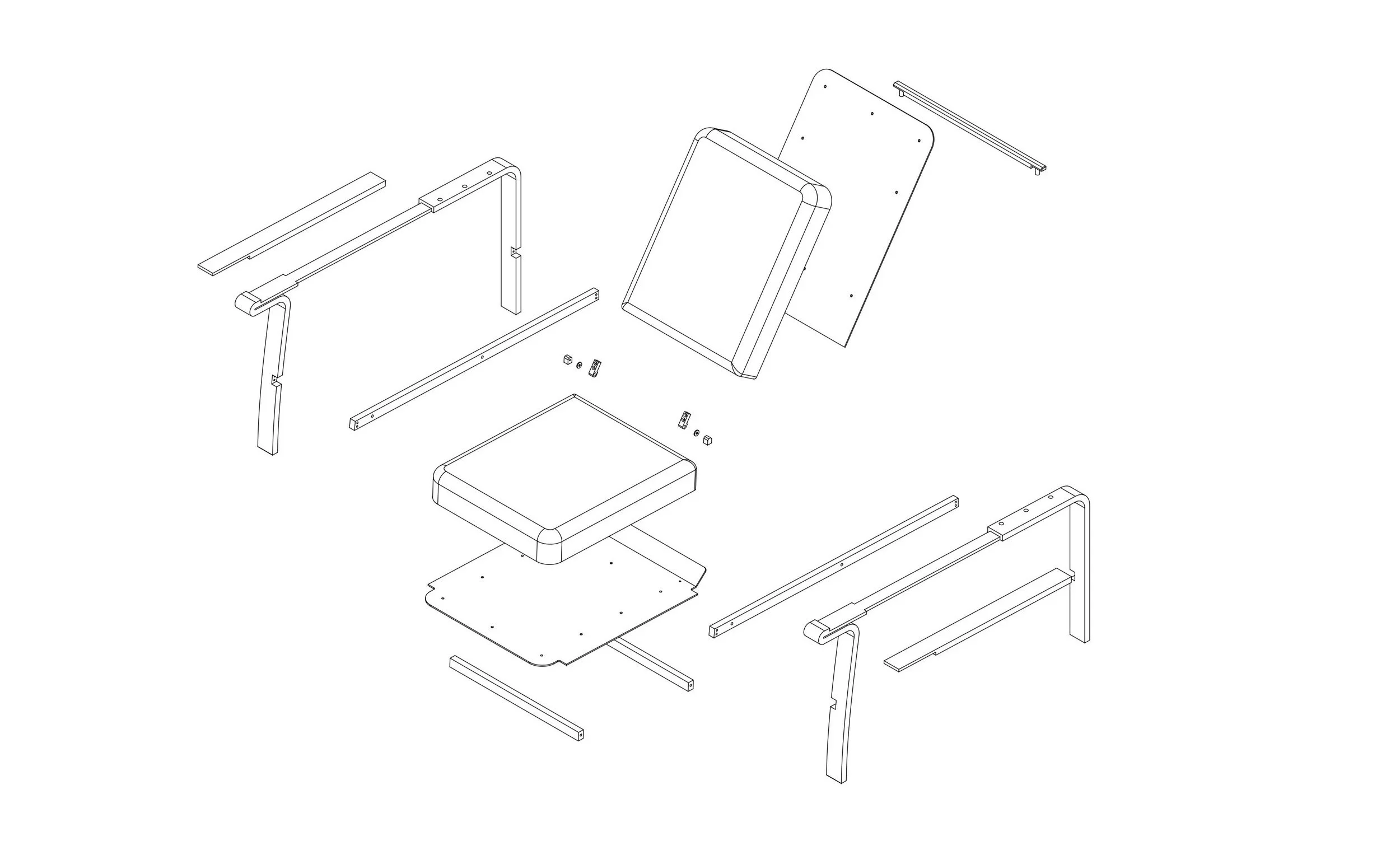
My idea was to make two parallel parts that form the armrests as well as the legs of the recliner, and then make an upholstered seating surface and backrest that connect the two armrests to each other. The angle of the backrest would be adjusted by moving a metal bar with a 12mm pin on either end of it into one of three sets of holes drilled into the rear part of the armrests. The parts of the armrest that your arm touches when you sit in the chair would be covered in blackened oak wood so that you don't come into contact with cold steel when you're sitting in the chair and reading your book or listening to music.


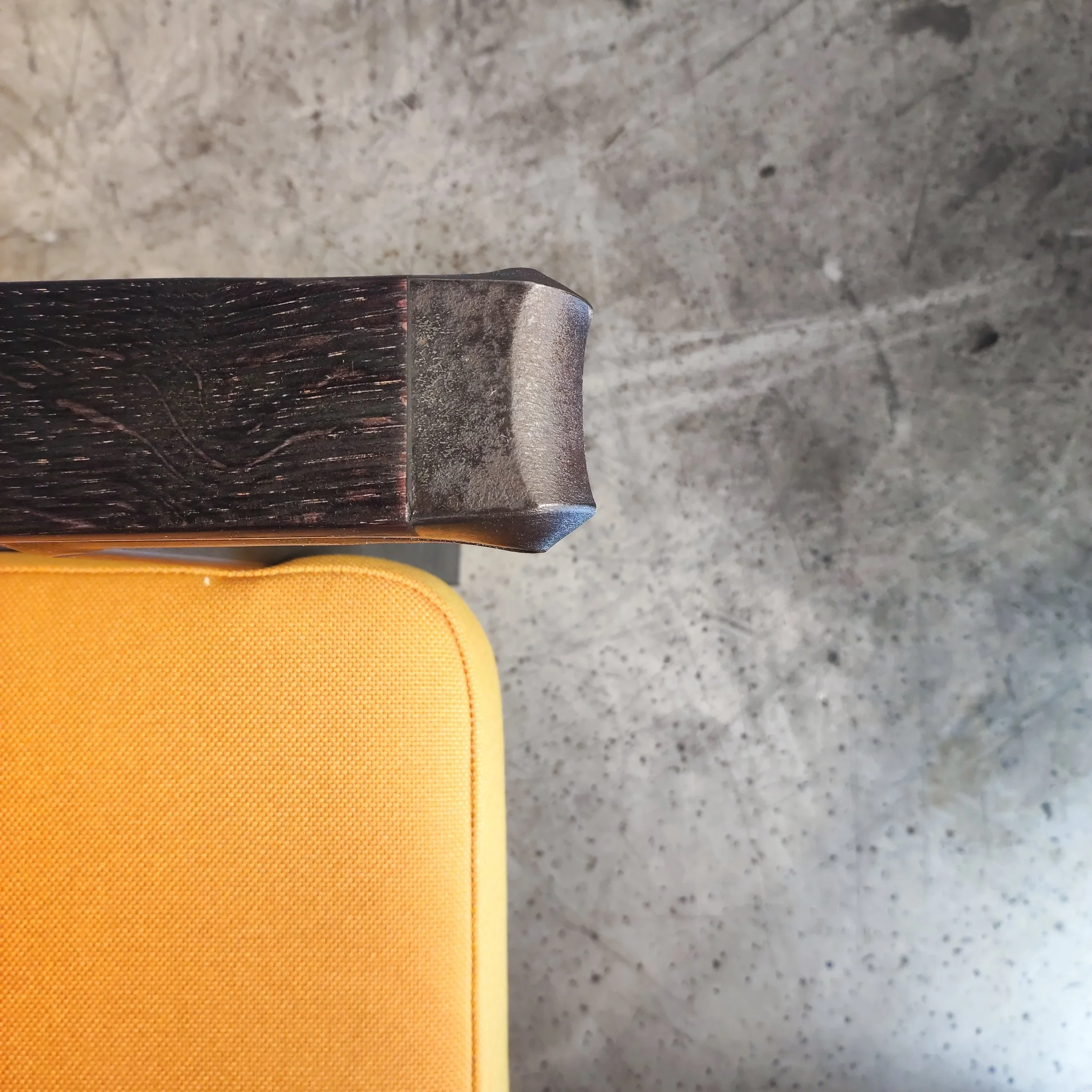
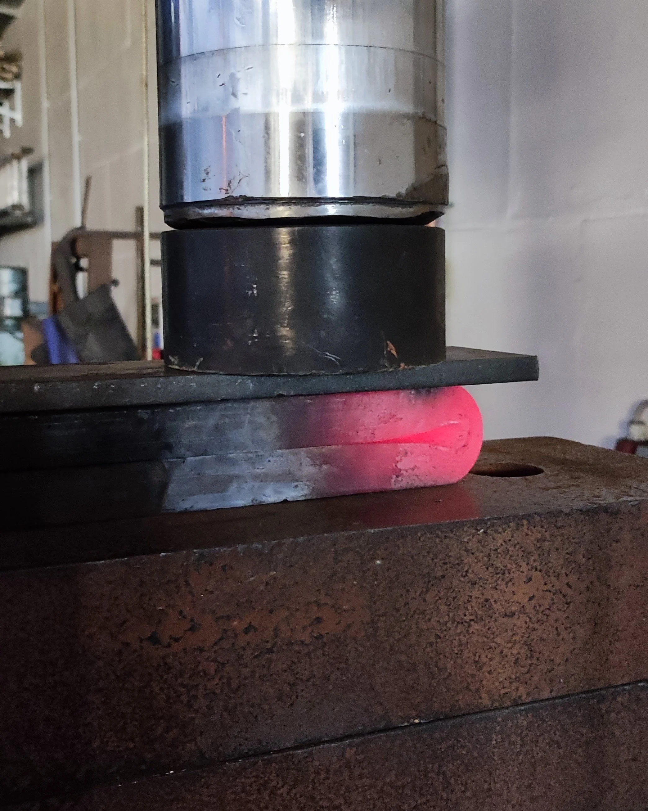
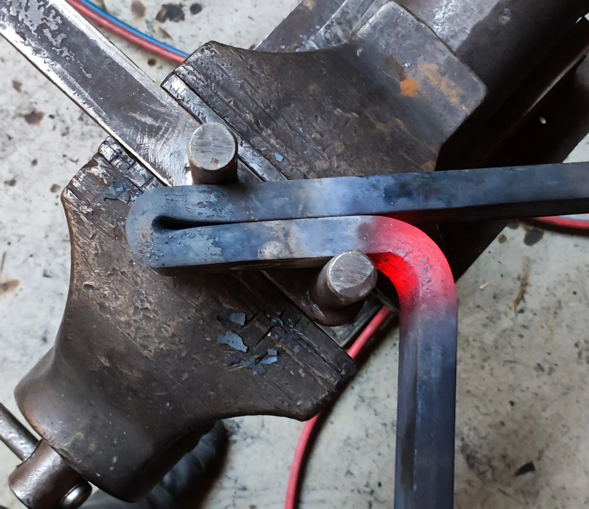
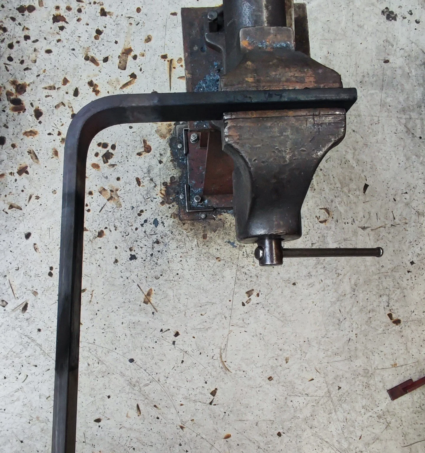
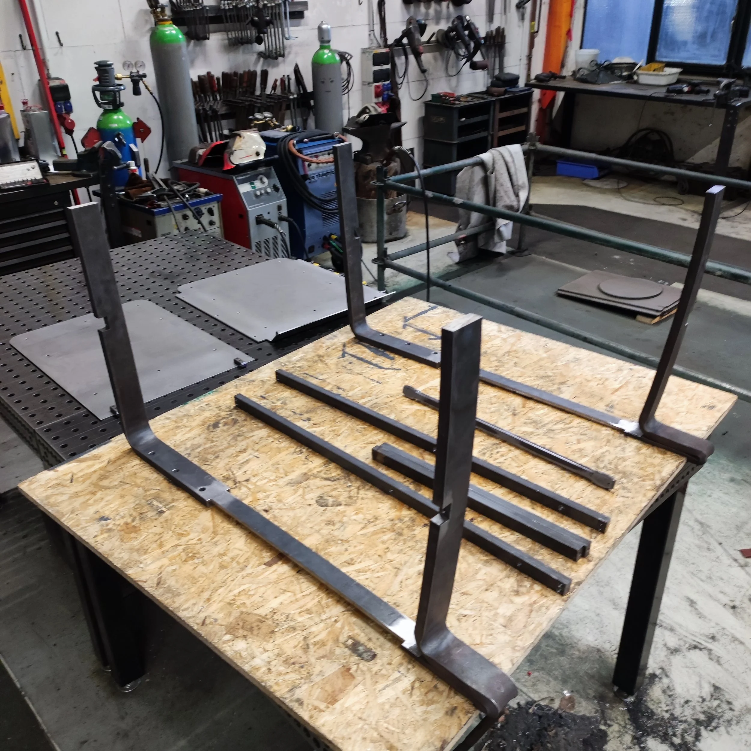
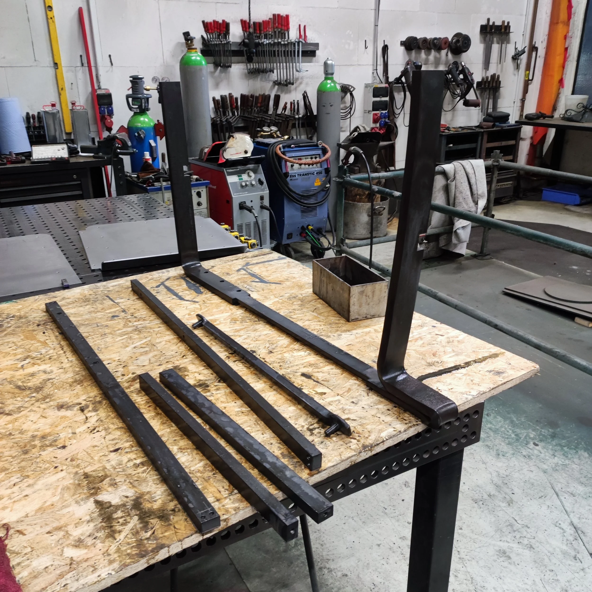
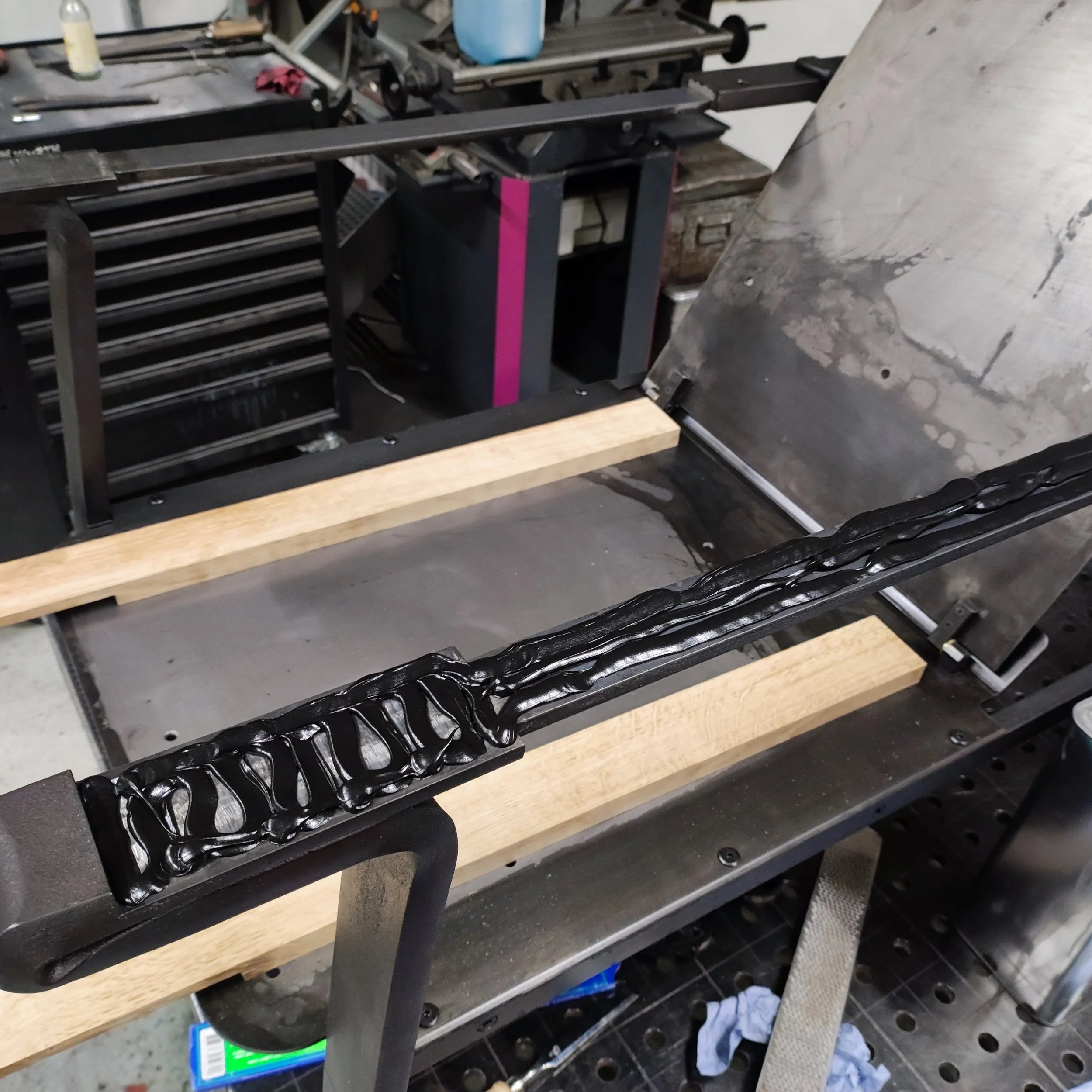
The first steps in actually building my piece were to cut material, deburr it to get rid of any sharp edges, build a bending jig and then light the forge. The bending jig was necessary to ensure that the curve on the front legs of the chair would be precisely the same on the left and right sides. Once I had finished building the jig, I took my piece of flat bar 70x20mm (fl70x20) that would become the legs and started with the hot bending process. The first bend that I did was the 180-degree bend that forms the front part of the armrest. It was important to me to ensure that I bent this in one heat and without hitting it with a hammer to avoid leaving hammer marks in the material. To achieve this, I heated the material to around 900°C, pre-bent it with the help of a bending fork and a large vice, and then used a 100-ton hydraulic press to squish the material back down on itself. This makes the material bend in a way that really shows the natural plastic movement of the material quite nicely. After that, I had to make a near 90-degree bend for what would become one of the front legs of the chair. I then attached the pre-bent part to the jig that I built and started bending the curve of the front leg with the use of an acetylene torch and a big bending fork with a long handle for leverage. I then repeated these steps to make a set of near identical front legs.

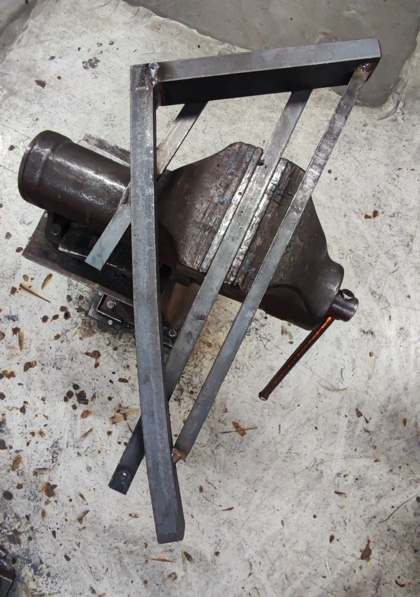


Once I finished bending the fl70x20 parts that would form the legs and the front parts of the armrests, I bent the parts that would make the back parts of the armrests and rear legs. Once I had the parts for the front and back legs, I cut off the excess material to get to the exact measurements that I needed. A full-scale printed technical drawing of the armrest/legs helped me to to determine where exactly to cut with the horizontal bandsaw.

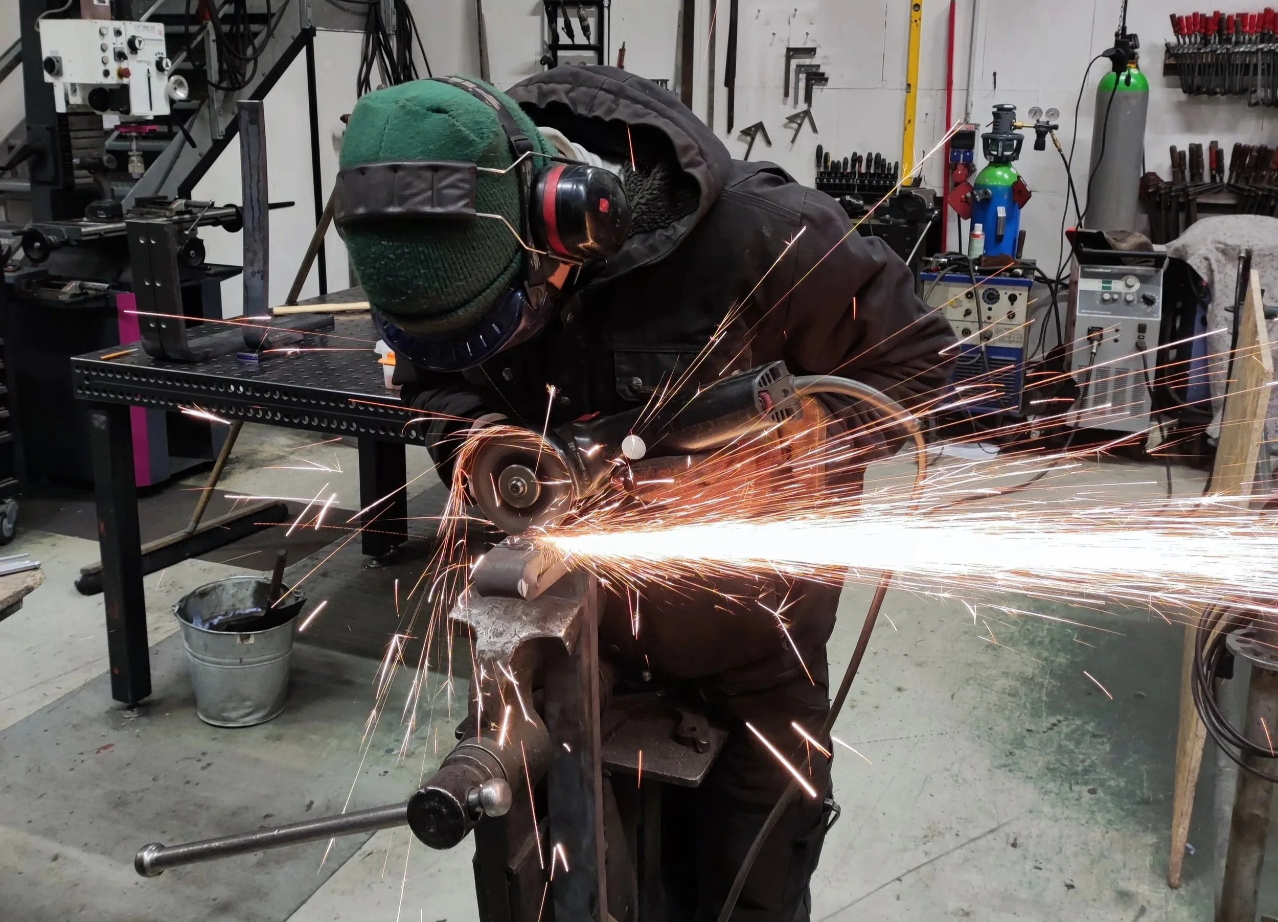
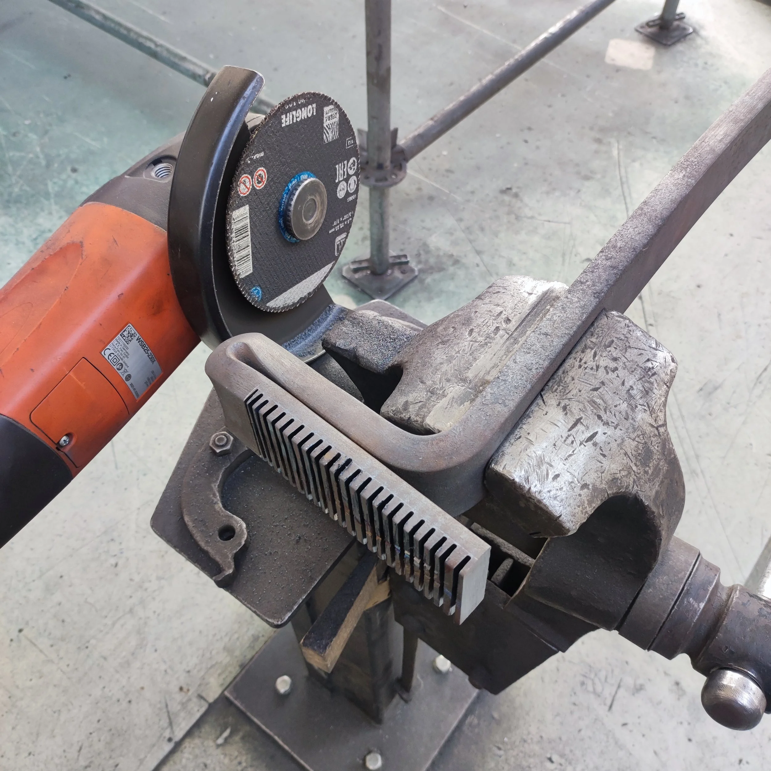
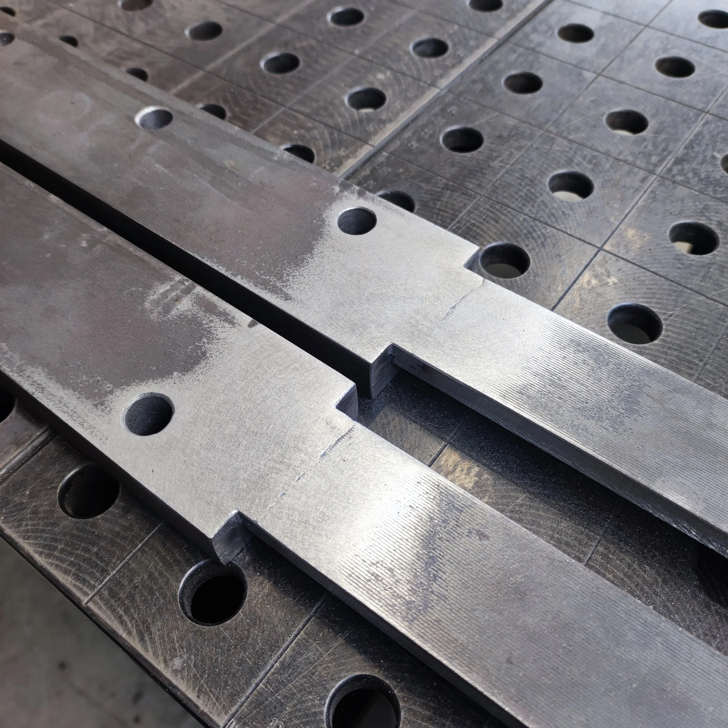
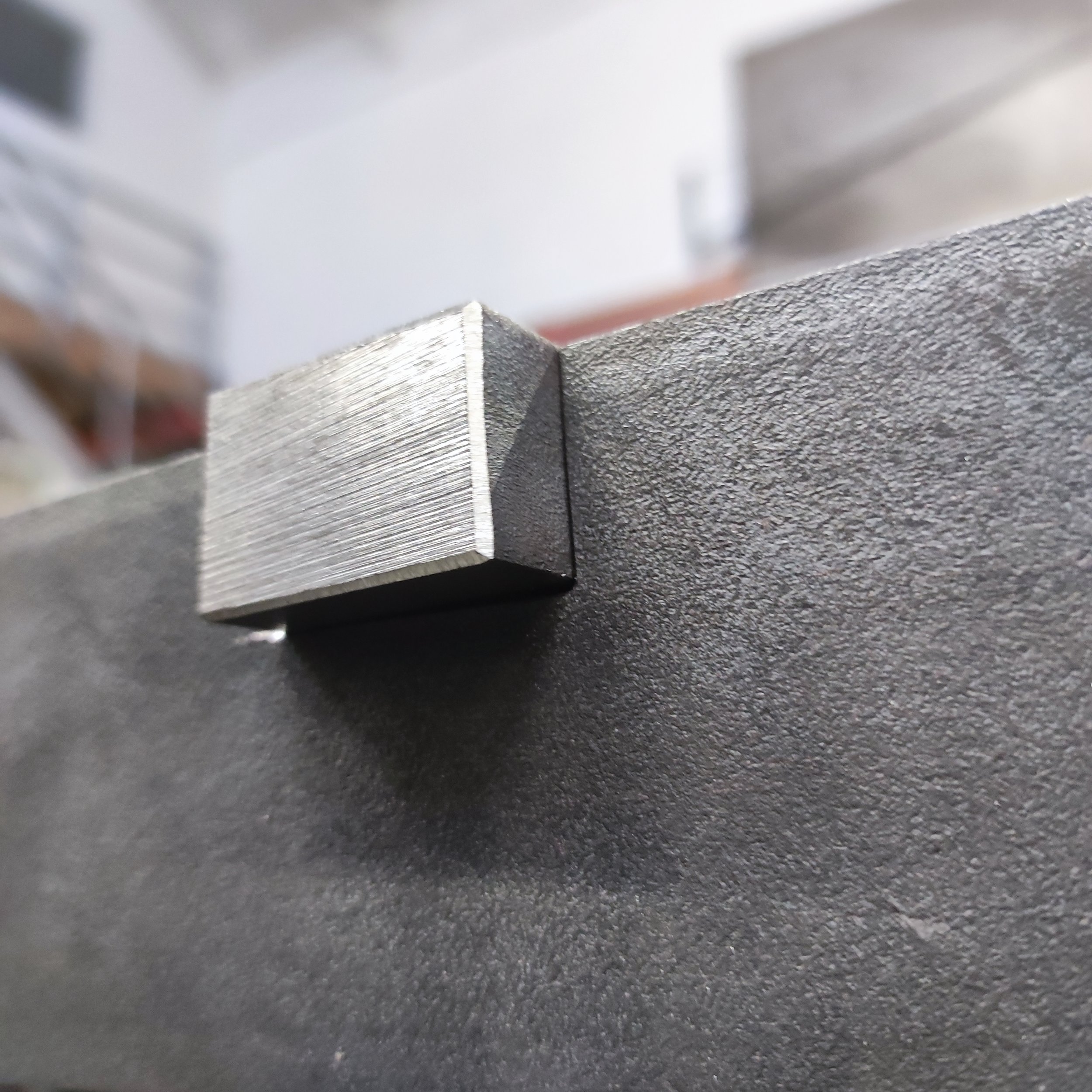
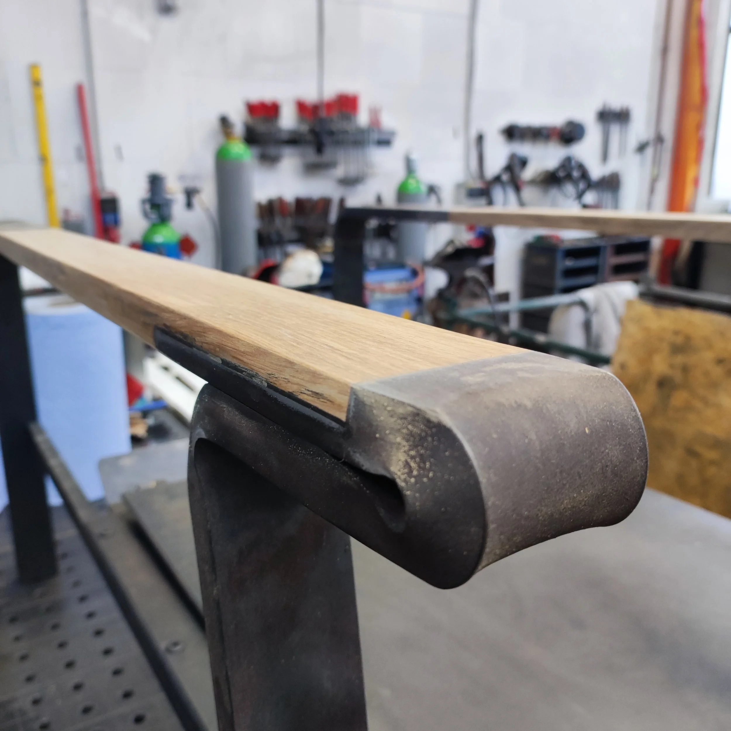
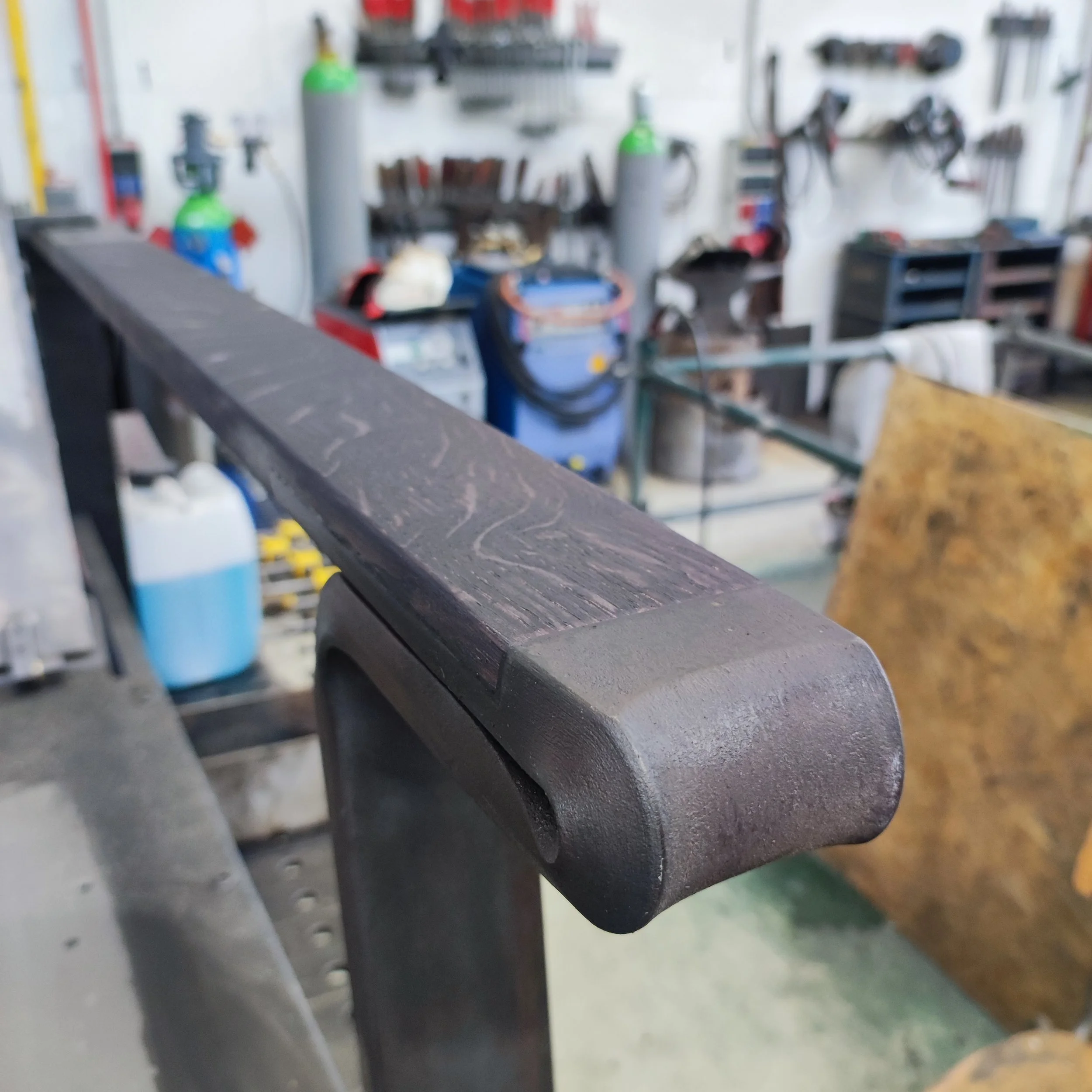
Once I had the front and rear leg parts bent, I had to make a 10mm step in the material towards the front part of the armrest to make space for where the oak armrest would go later. This step is important because it allows me to make the wooden armrest go almost completely to the front while maintaining the outer measurements of 70x20mm. It's a lot of grinding and filing, but it was definitely worth the effort.
I scribed my measurements onto the material and then cut, ground, and filed away for a number of hours until I had the necessary dimensions. Then I did it again for the other side.


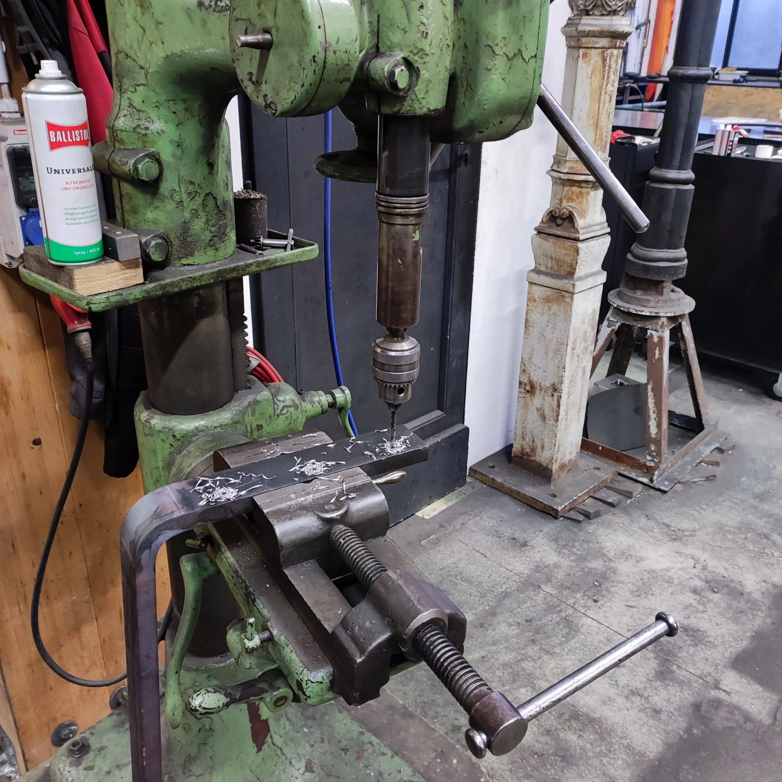
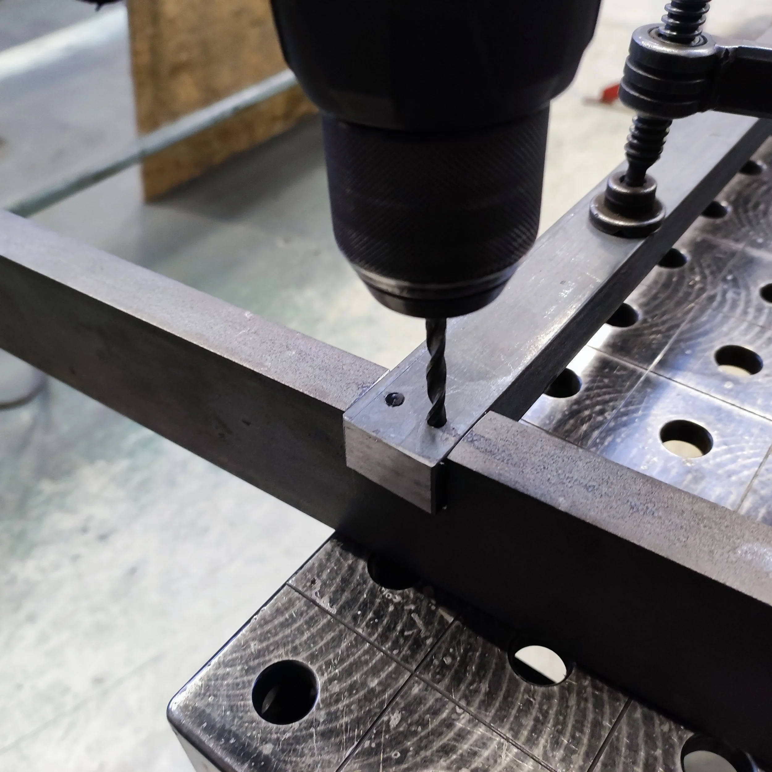
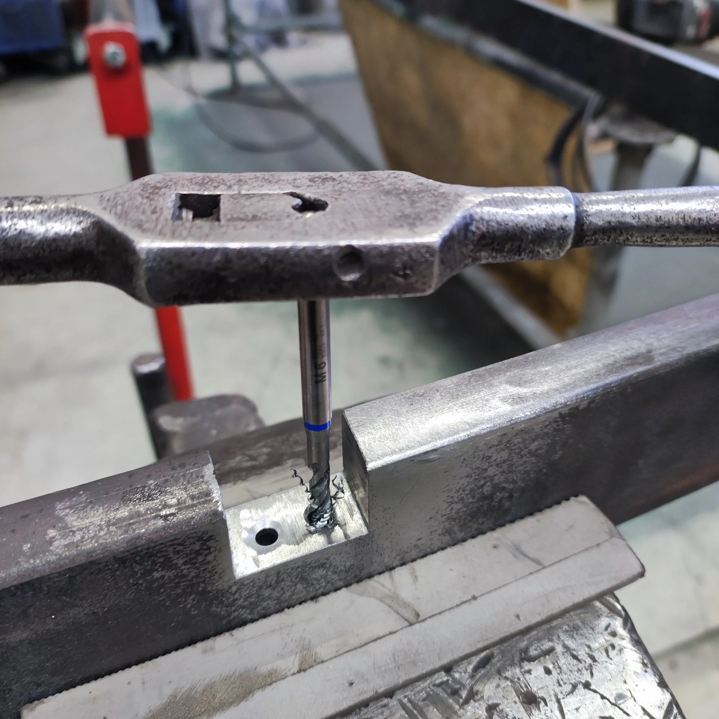
After all the loud and dirty grinding and filing work, I had to drill and deburr three 13mm holes in each one of the rear leg/armrest parts. These holes are where the 12mm pins from the adjustment bar would later fit into to adjust the angle of the backrest.

The parts for the front and rear legs were now prepared for the next step which was welding. I cut two fl40x10 parts that would be welded between the front and rear parts of the armrests. This part out of 40x10mm flat bar would form the structural base that the oak armrests would later be glued onto which would cover them on three of the four surfaces of the flat bar. When viewed from the side, you would later only see wood.
I clamped down the front leg, 40x10 armrest structural support, and the rear leg parts onto the welding table and welded it with a MAG welding machine. After welding, I ground the welds flush so that they are no longer visible.


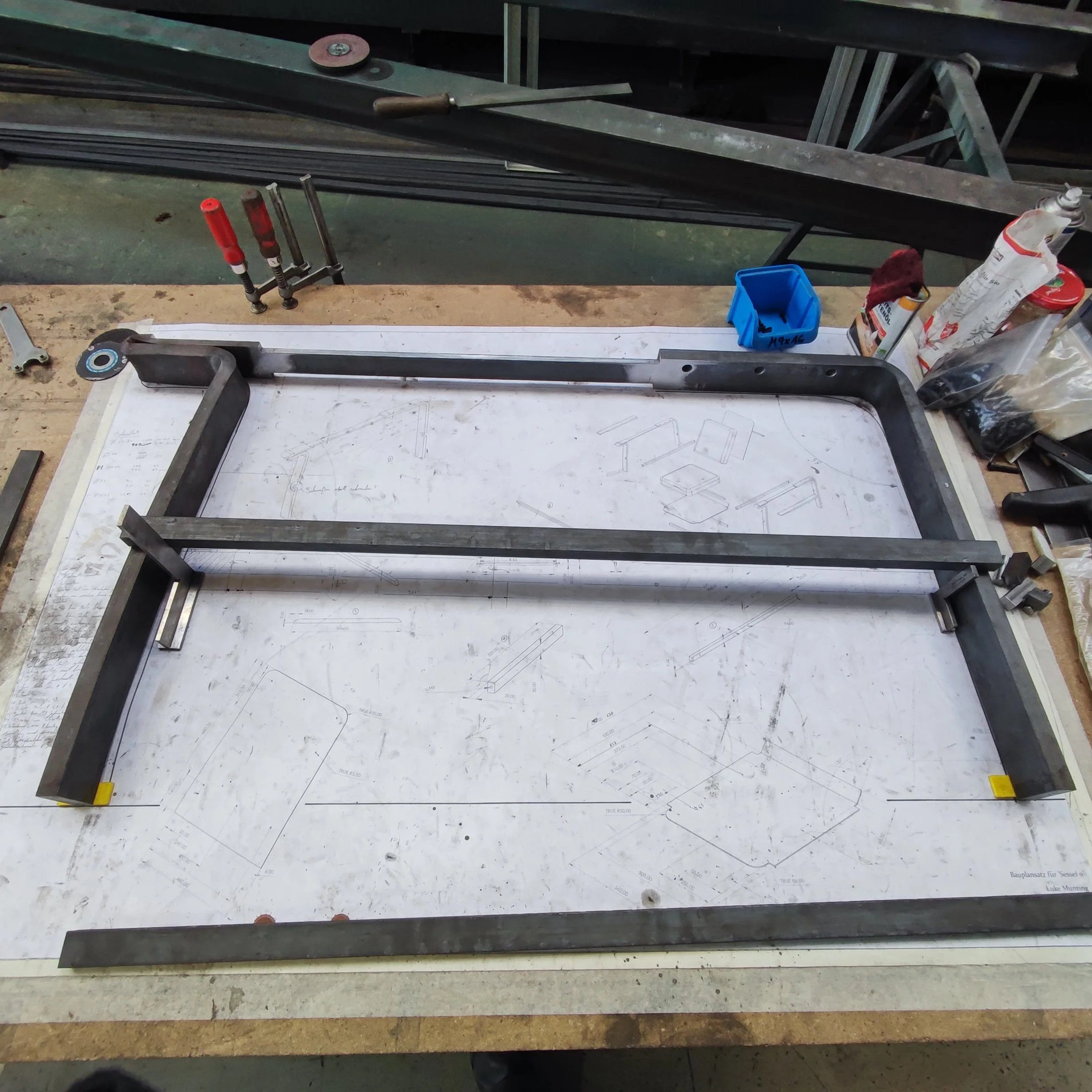
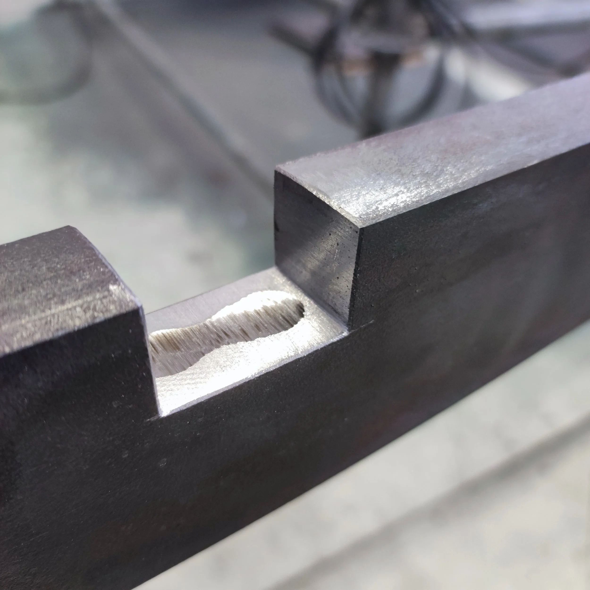
With all the welds done and ground flush, it was time to attach the fl30x20 supporting struts that run parallel to the top of the armrest. These flat bar struts are where the seating surface would later be attached with M6 furniture screws. In order to attach the struts, I had to make notches in the front and rear legs of the recliner, so I scribed my measurements onto the material and then started grinding and cutting away once again. After removing the bulk of the material with a grinder, I filed away the last little bit so that I had nice, precise notches in the legs for the fl30x20 struts that had to fit perfectly flush with the inside surface of the legs.
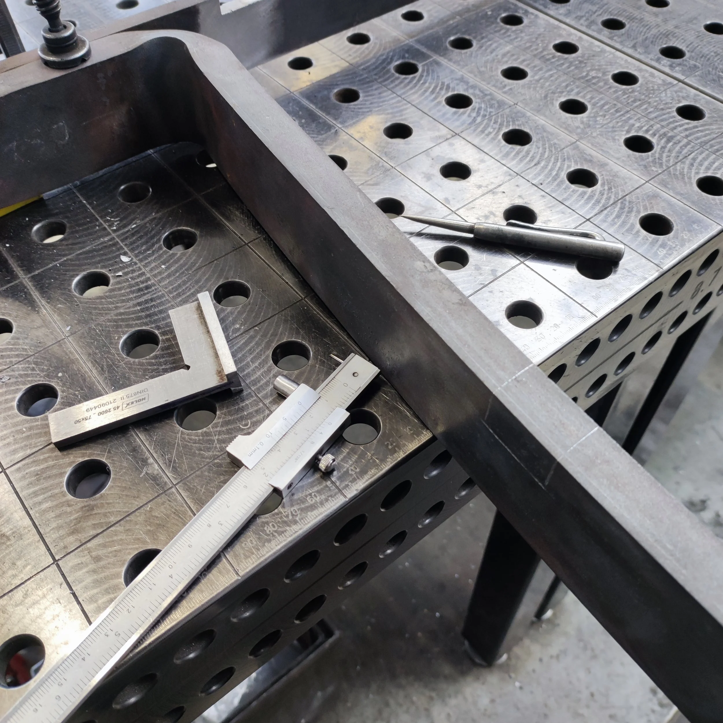
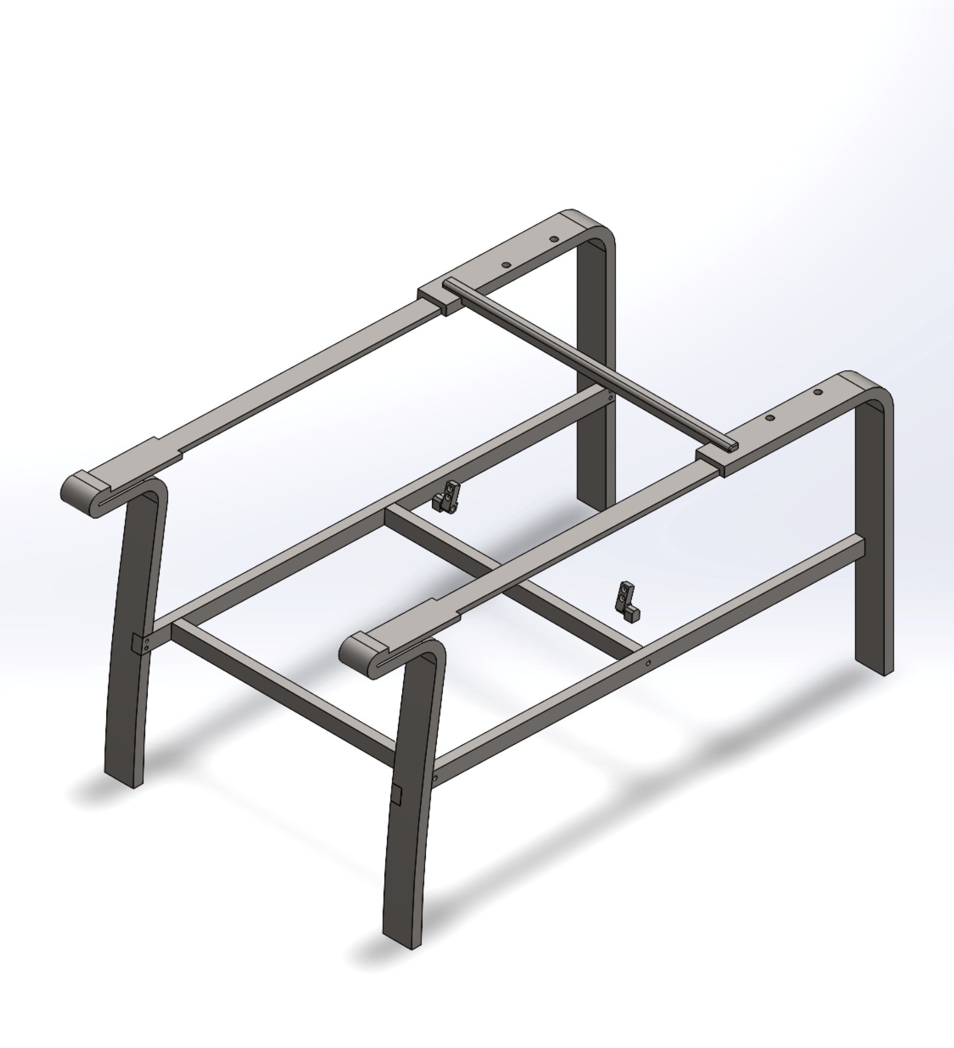
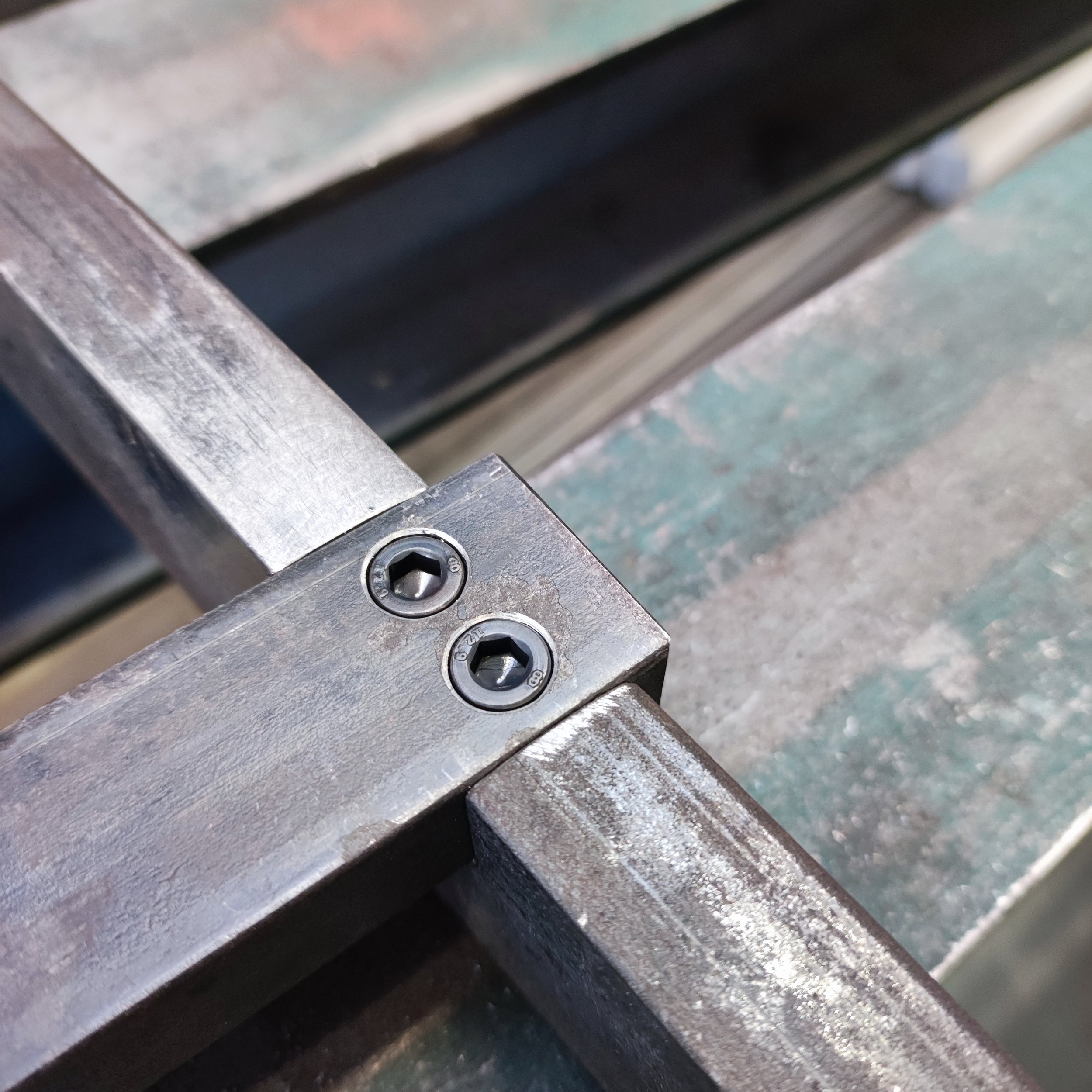
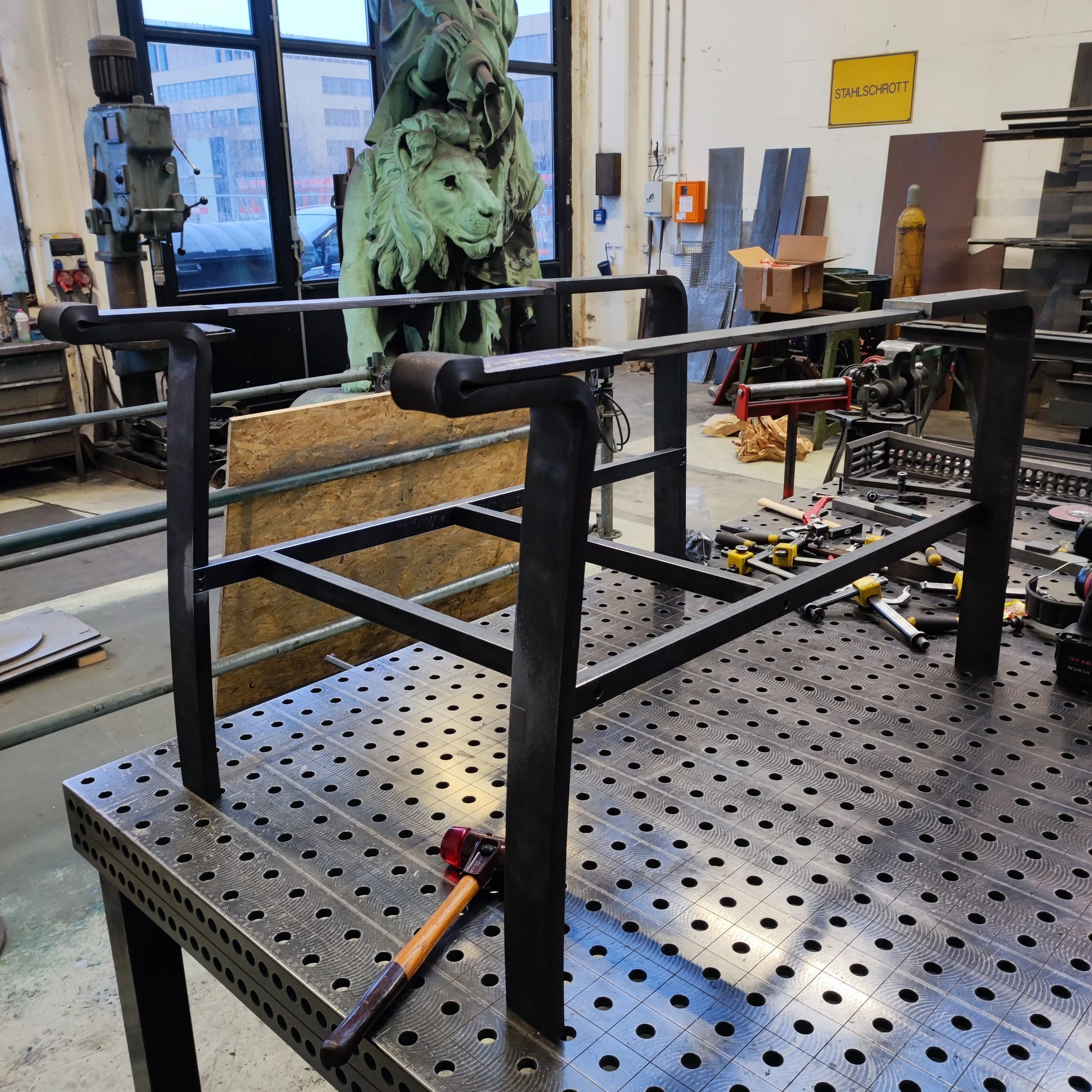
After notching the legs was done, I had to drill holes so that I could attach the struts to the legs with blackened M6x20 machine screws that have a cylindrical head that I countersunk into the struts so that they are flush with the surface(see the photos to understand better). With the threads cut and the horizontal supporting struts in place, I had to grind down the excess material on the front and back of the struts so that they are flush with the front and back surfaces of the legs. I then also attached the two fl30x20 parts that connect the two struts (and therefore the armrests) to one another and provide a support structure underneath the seating surface of the chair. These parts were attached with blackened M8x30 screws that were countersunk into the struts. With this complete, the basic frame of my chair was now complete!


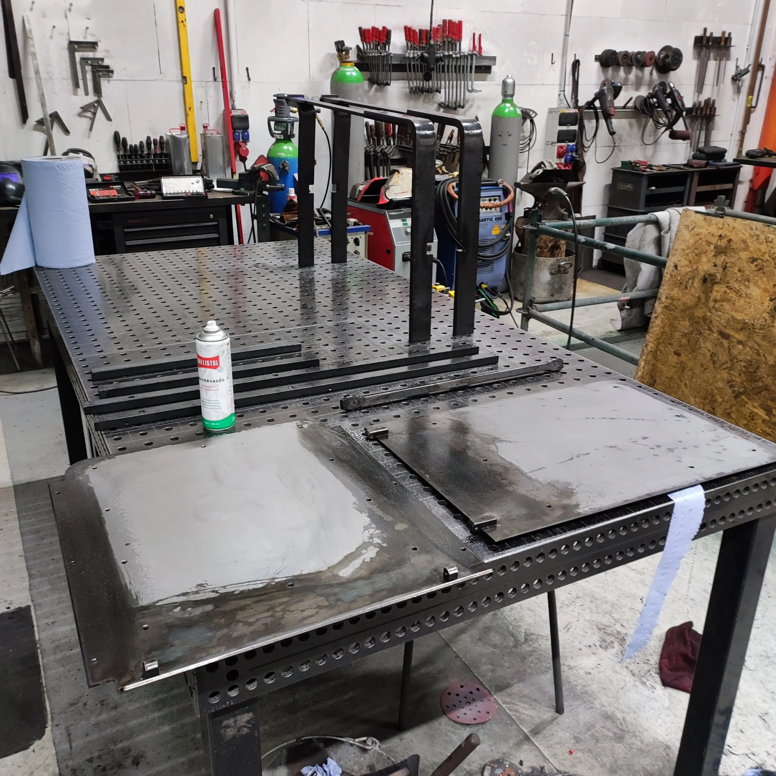
The recliner was starting to take shape. With the frame constructed, it was time to grind bevels onto the 4mm sheet metal parts that had been laser cut and bent for me by a third party sheet metal company. In order to grind perfect bevels, I scribed a line that ran 3mm parallel to the edges that I wanted to bevel. After grinding the bevels to break the sharp edges, I attached the seating sheet where the upholstered boards would later be attached to the fl30x20 structure that I constructed in the previous steps. The seating sheet was attached with six black steel M6x20 wide-flanged furniture screws that use an Allen key bit and have a flat head that does not need to be countersunk. These are the same screws that I would later use to attach the upholstered seat and backrest parts to the laser cut sheet metal parts.


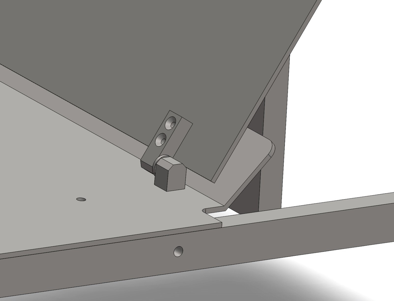
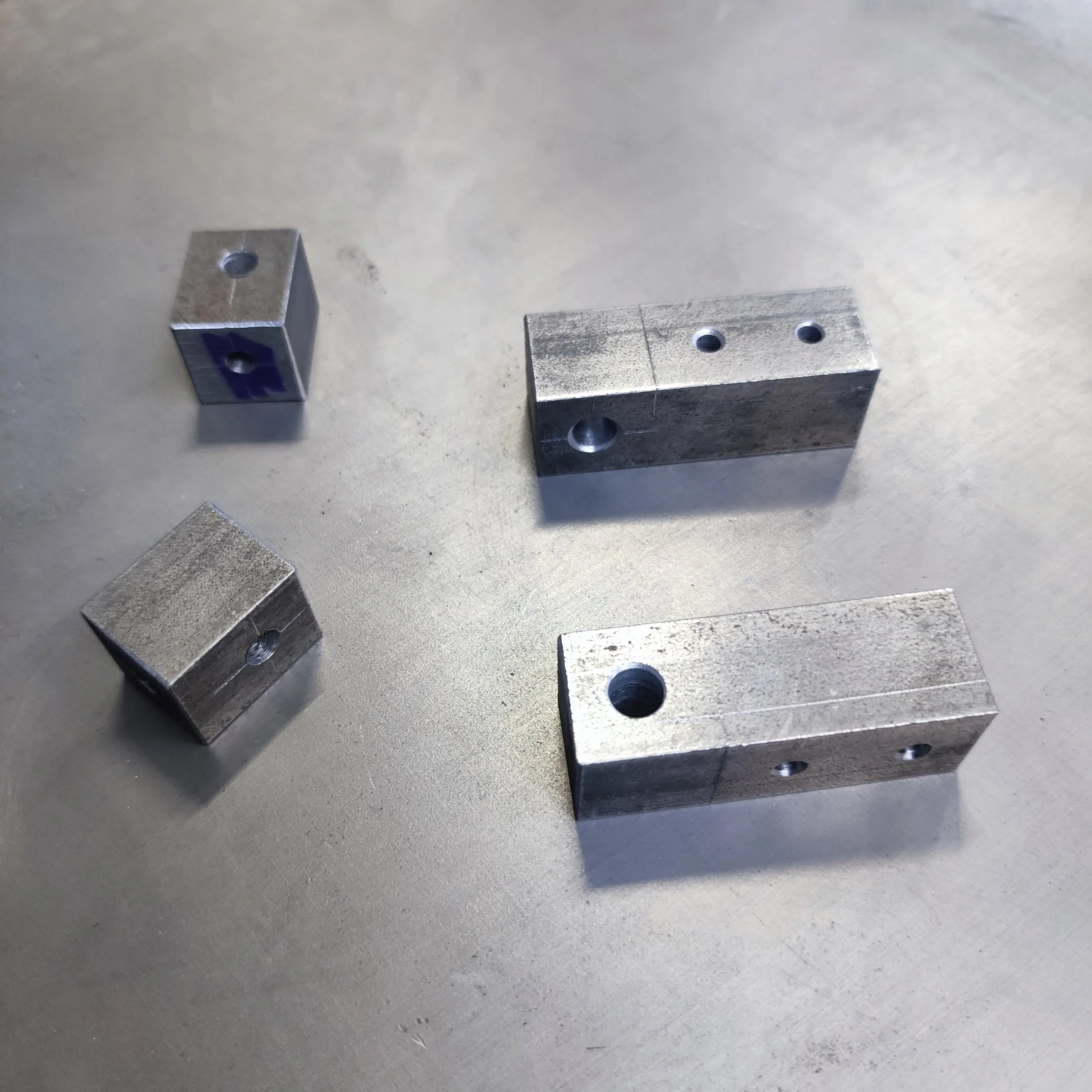
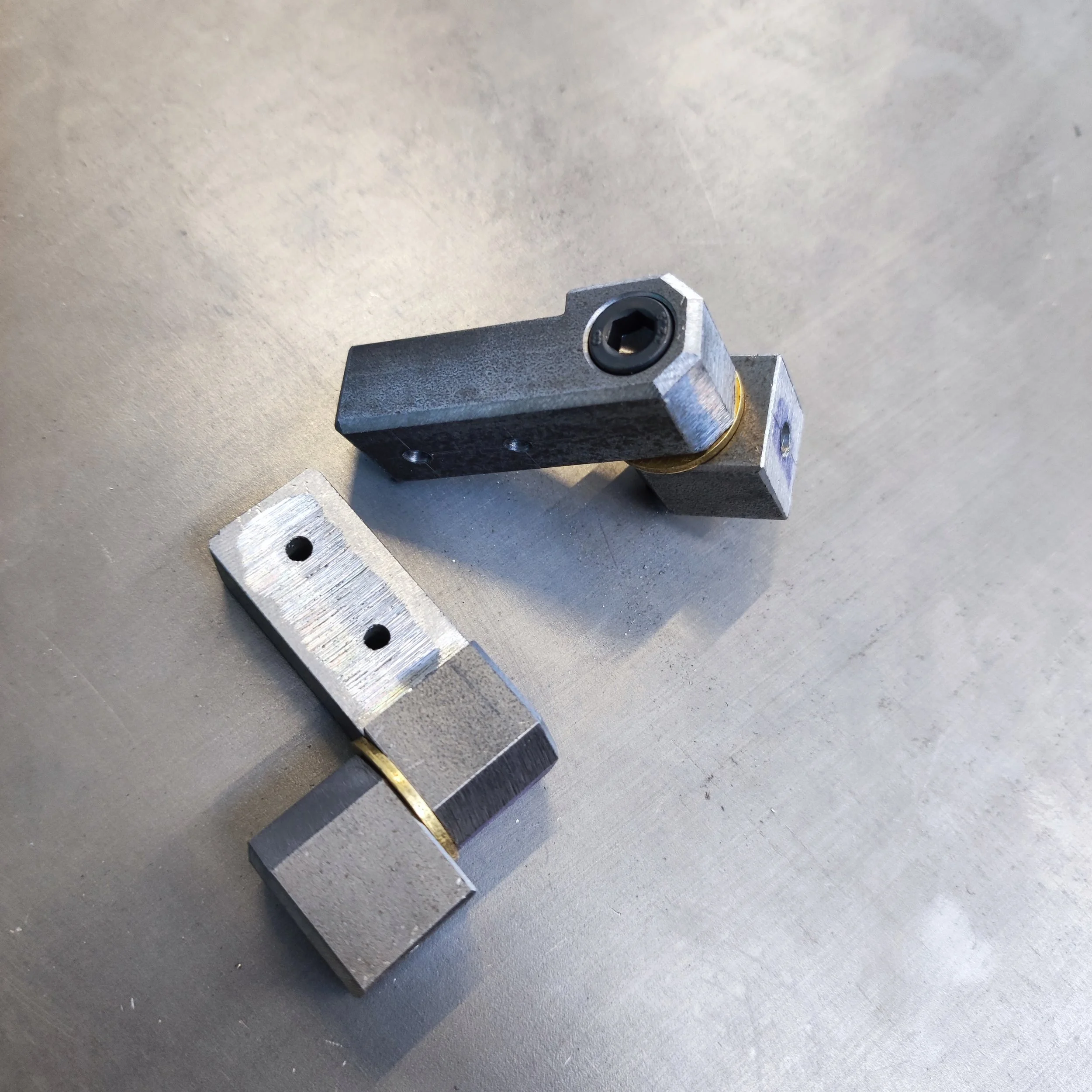
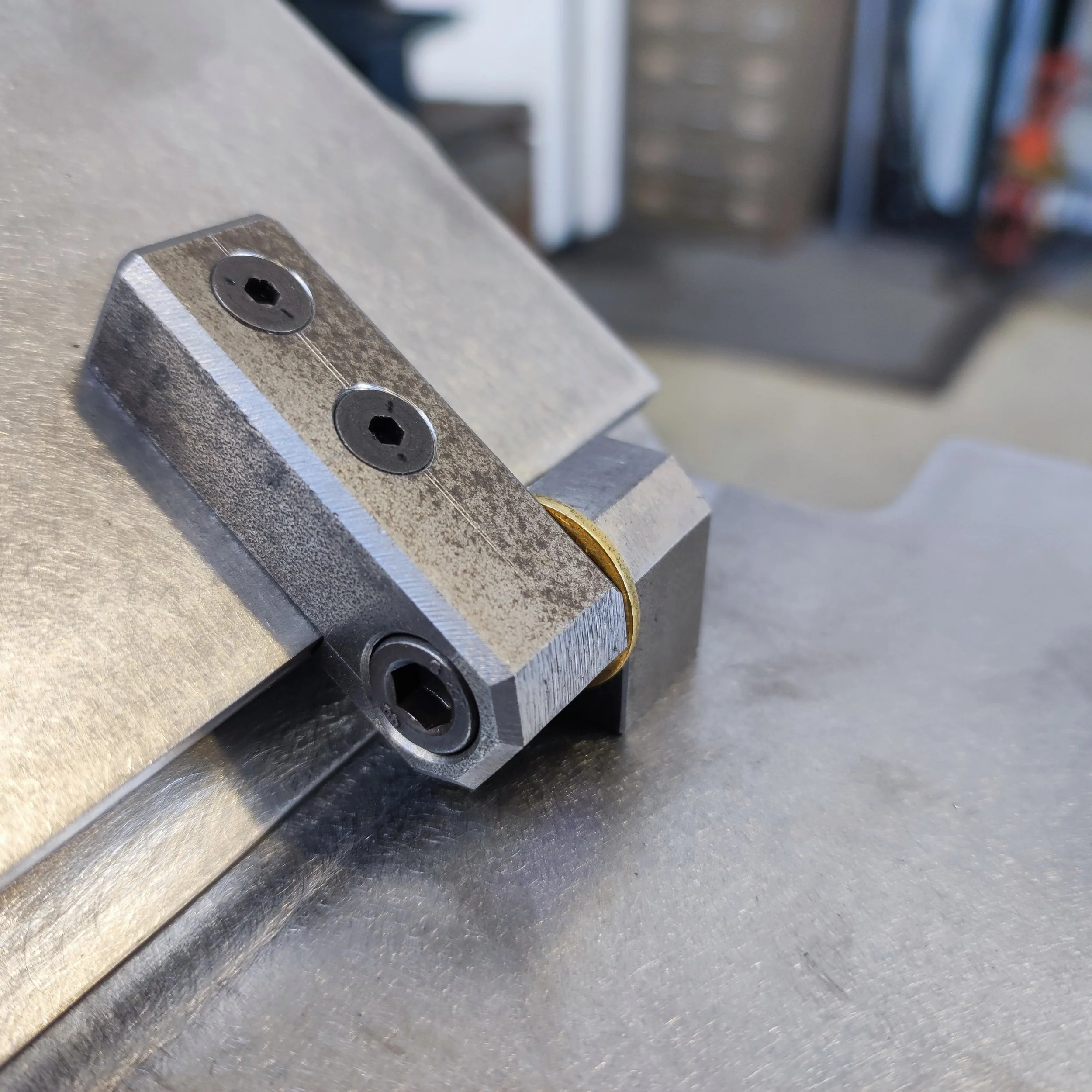
Now comes one of my favorite parts of the entire build: the hinges. The hinges that attach the backrest to the seat and allow for the angle of the backrest to be changed while keeping it fixed to the seat are made out of 16mm square material. They are made out of two parts that attach to the backrest and two parts that attach to the seat and they are held together by an M6 countersunk machine screw. The part of the hinge on the backrest and the part on the seat are seperated by a brass washer that acts as a type of mechanical lubricant between the steel surfaces so that the movement of the hinges is buttery smooth.


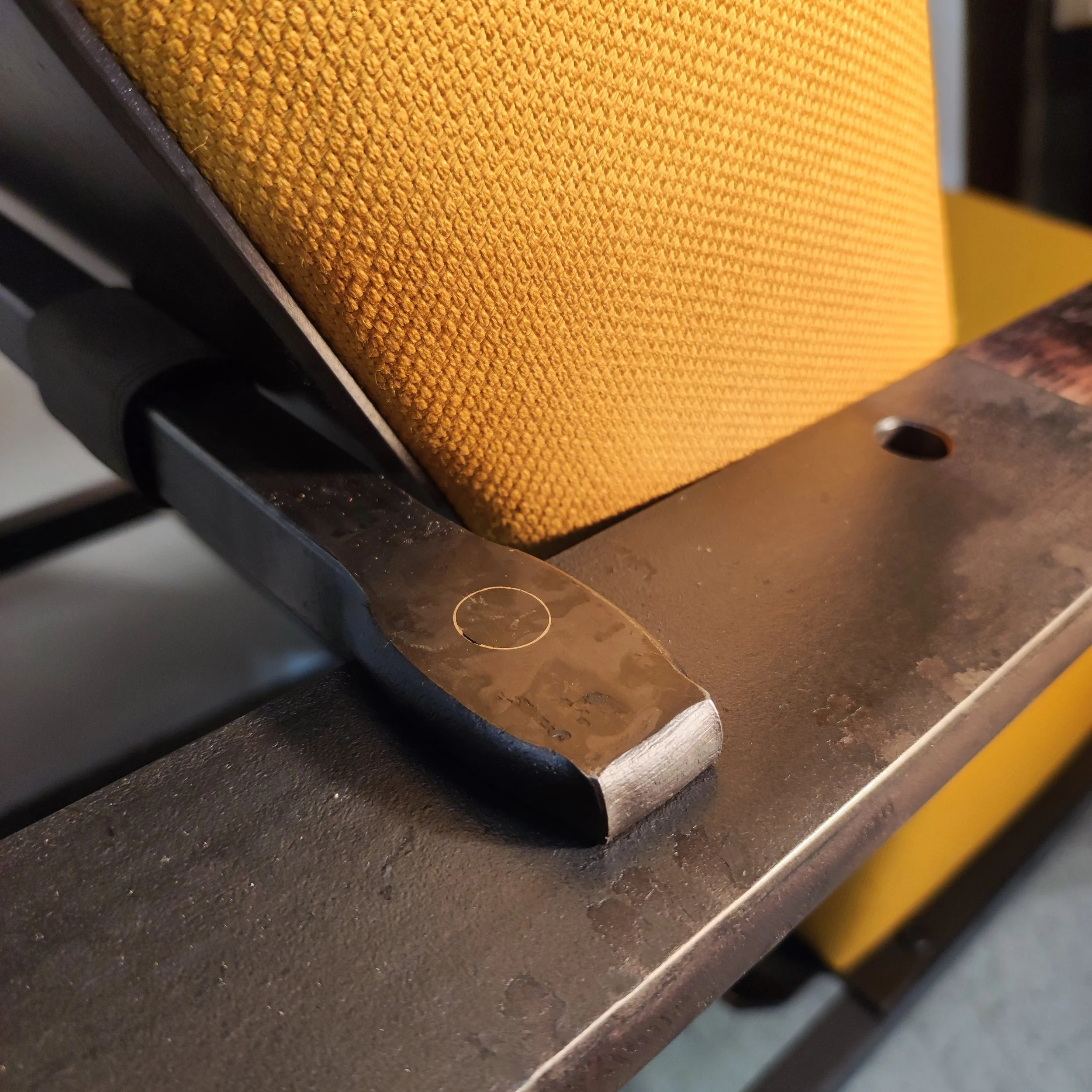
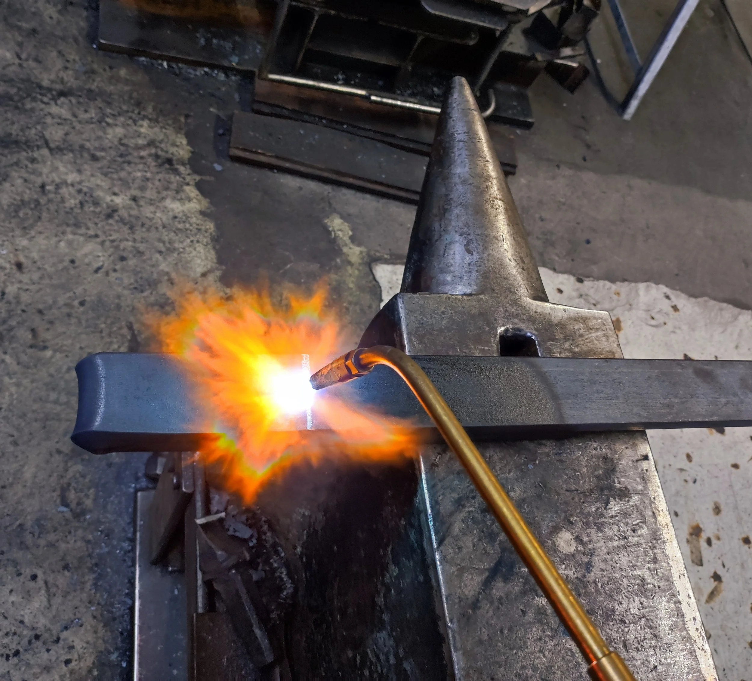
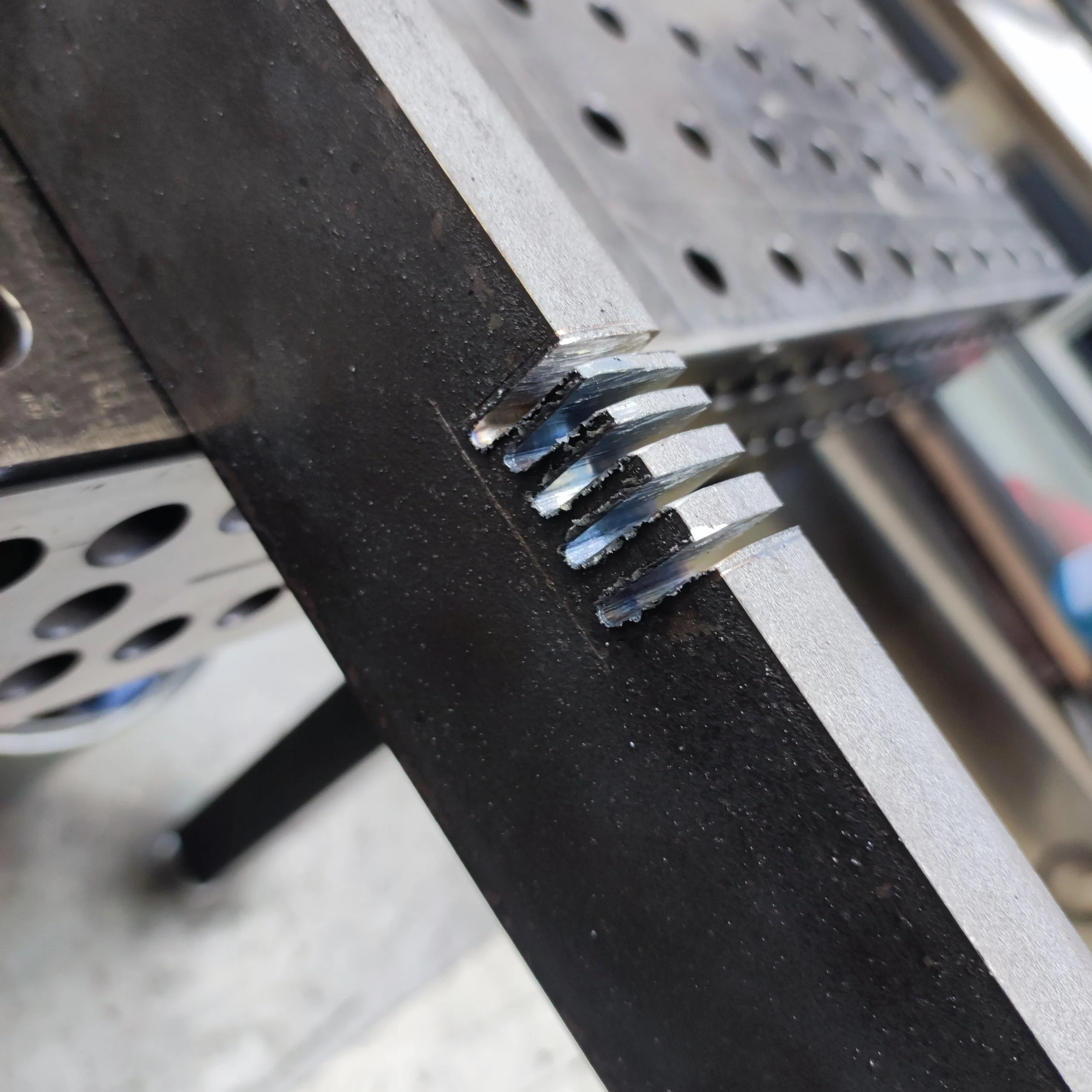
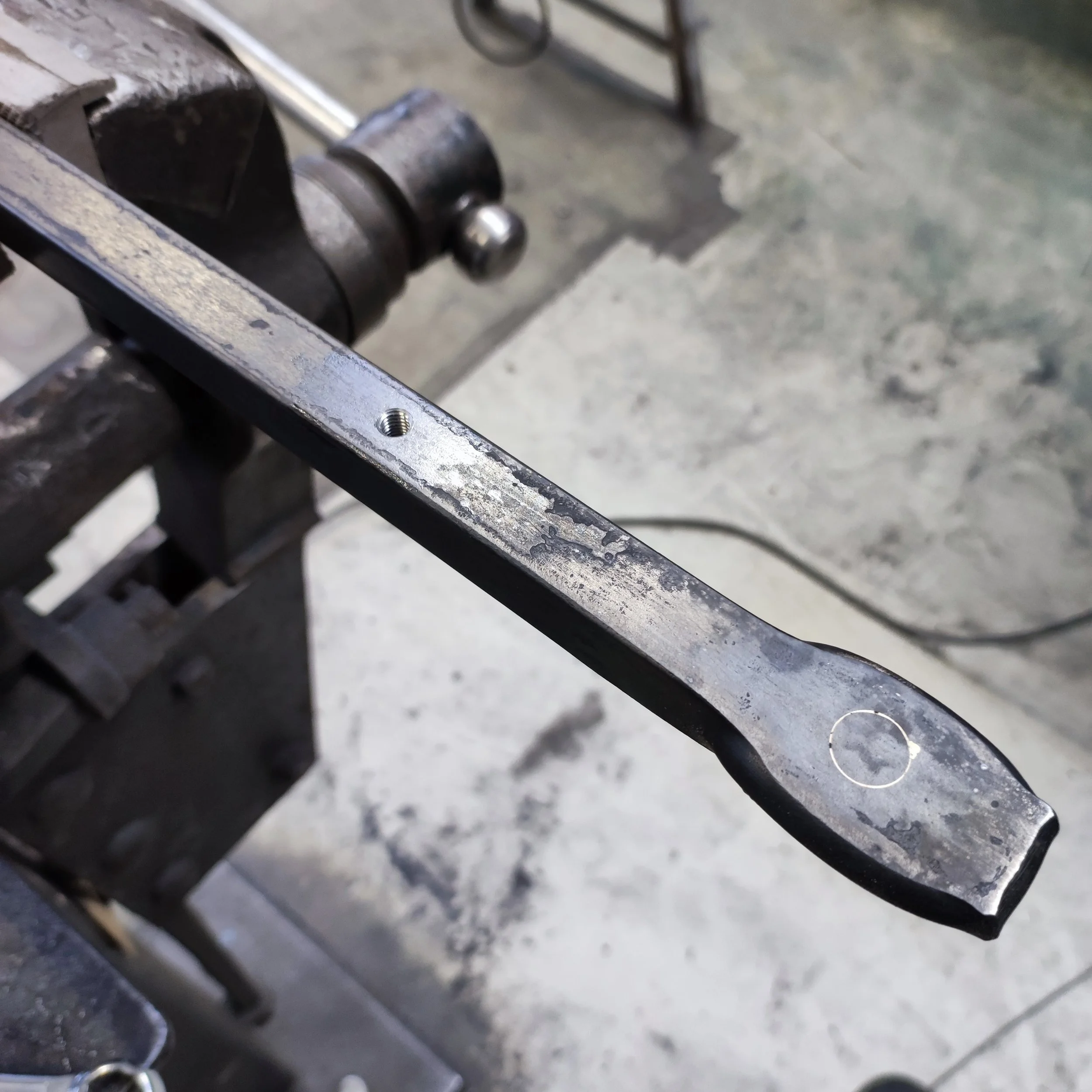
The sheet metal parts were attached and the hinges were working smoothly, so now I had to make the adjustment bar that would go behind the backrest, allowing you to adjust the seating angle into one of three possible positions. I made this part by taking a 16mm square bar, heating the ends to forging temperature, and squishing them in the 100T hydraulic press to make an offset in the material. After doing this, I drilled a 12.2mm hole in each of the offset ends and brazed a 12mm pin into place. The excess of the 12mm pins were then ground flush with the top of the bar, revealing a ring of brazing that would make an interesting detail once the project was completed.


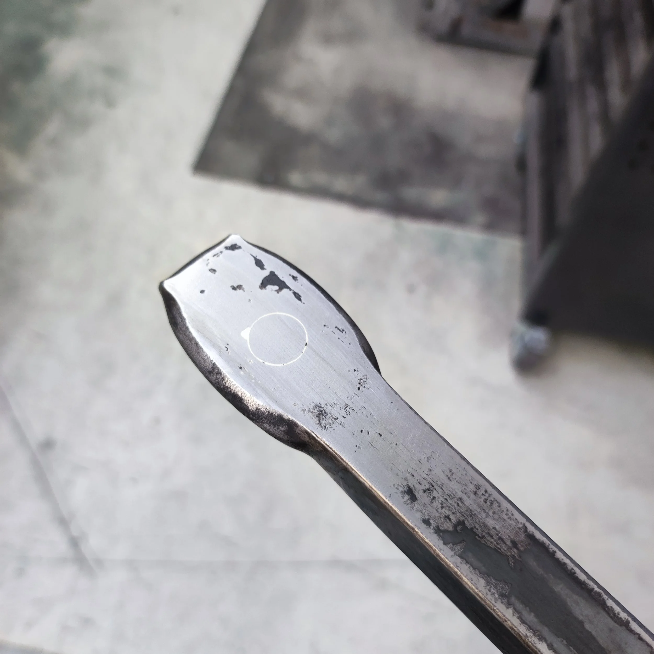
Now that I had finished building the adjustment bar, I had all the steel parts finished for my chair! All that I needed to do now was to blacken all the parts with gun blue, which is a liquid chemical that reacts with the steel, causing the surface to go dark black. It only reacts with the steel though, meaning that the ring of brazing from the previous step would still be clearly visible on the finished surface. The first step of the gun bluing process involves cleaning all the parts with acetone to remove any oil or fat residues that are on the surface, because the gun blue can't react with the steel if it has oil on it. After the gun blue has been applied, it reacts for a few minutes and then it needs to be washed off with a lot of soapy water to neutralize the acidic gun blue. After neutralization, the parts are all rinsed with clean water and then thoroughly dried so that they don't rust. If any gun blue is left on the surface, it will rust, so rinsing properly is important. The inside surfaces of the backrest and the seat were not blackened completely because they would be covered with upholstery later and therefore not be visible.
With the steel surfaces all blackened, it was time for me to do some woodwork. I am not a carpenter or joiner, so I always have a certain amount of respect for woodwork, especially when I only have one shot at it. I had the blanks for the armrests made by a joiner friend of mine, but I had to do the final fitting, gluing, shaping, sanding, and surface treatment myself. I decided to use oak wood for the armrests because it is a fairly hard and durable wood that looks great. First, I had to glue the blanks onto the steel armrests that I had built. For this, I used a black bond and seal glue. It is important to use a flexible glue for this type of connection because the thermal expansion rate of steel and wood is different so if I were to use a hard glue like a two component epoxy, it would most likely cause the wood to crack after a while. Once the glue was dry, I used an orbital sander to sand away the excess wood of the armrest so that the outer dimensions were exactly the same as the dimensions of my steel armrests (70x20mm). After shaping and sanding to a fine finish, it was time to stain the wood black. For this, I used an interesting stain that is easily made by dissolving steel wool in normal household vinegar for about two days. Once it is fully dissolved, this liquid was applied to the oak with a brush and allowed to soak in for a few minutes and then the excess is wiped off. It reacts with certain chemical compounds found naturally in oak wood, causing it to blacken to a dark grey that almost perfectly matches the color of mill scale found on steel.

Now for the final touches! I sealed all the wood and steel surfaces with a wax and oil mixture that is actually meant for sealing wooden kitchen countertops or tables. The oil component soaks into the wood and under the mill scale of the steel, and the wax component seals the surfaces, protecting them from water and oxidation. This is a treatment that is great for interior products made of steel and wood because it is durable and food grade, meaning fewer toxic chemicals in your home. I far prefer this to any type of epoxy or paint because they are all made out of pretty hectic chemicals that you probably dont want in your home.
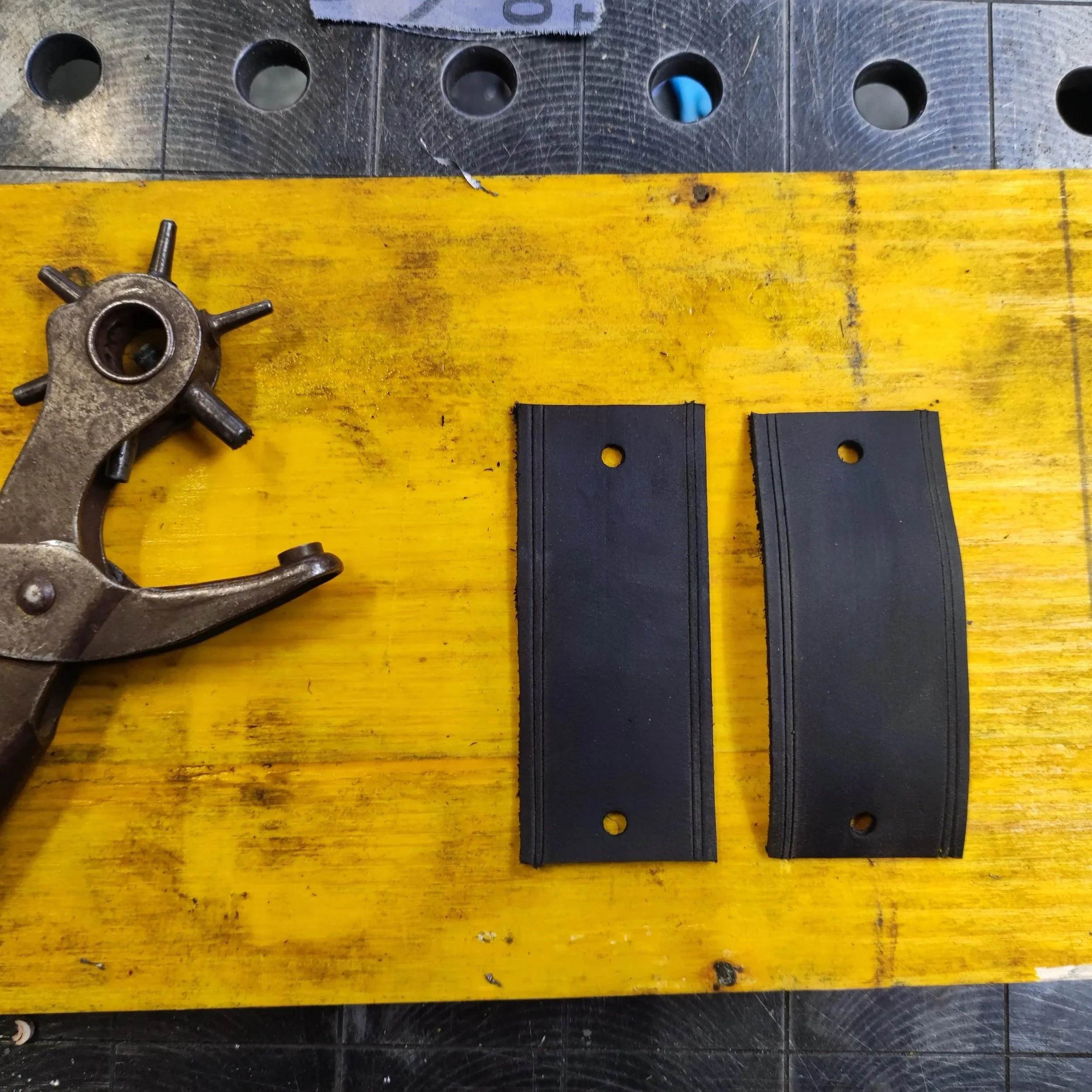
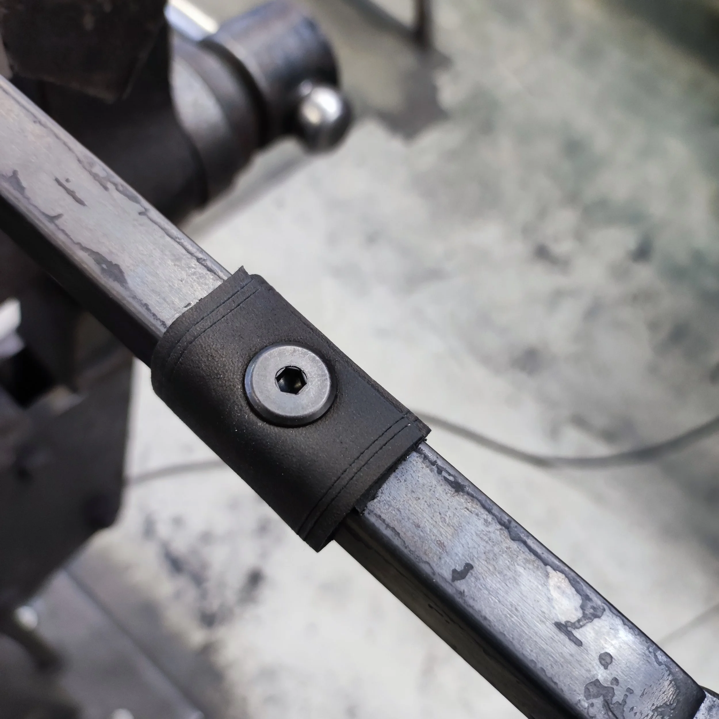
Once the surfaces were all sealed and protected from corrosion, I cut some leather strips that I attached to the adjustment bar with the same M6 flat head furniture screws. These leather strips are there to create a soft surface between the adjustment bar and backrest. Metal on metal would be too noisy and scratchy when making the angle adjustment to the backrest. I also glued some leather on the bottom of the feet and then cut off the excess to prevent the heavy chair from scratching the floor. The steel parts of the chair alone weigh 73kg!

The absolute last step to any project is always a special one, and in this project it was especially exciting because of all the work that had been leading up to this moment. I attached the upholstered seat and backrest surfaces to my sheet metal backing. For this, I used the same M6 wide-flanged furniture screws that I used to attach the leather strips in the previous step.
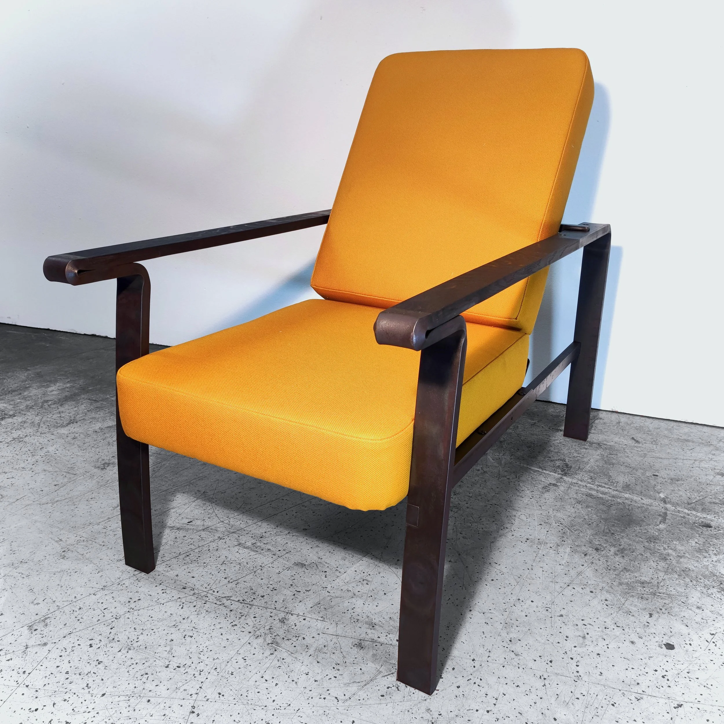
The chair turned out great and its wonderful to sit in. I might still change out the upholstery to some slightly more rounded cushions that are covered with leather in the future but all in all I´m very pleased with what I was able to produce in 37 Hours. I often enjoy sitting in my chair and it serves as a good reminder to me of all the things that I learned at Schmiede Lehmann in Hamburg from my teacher, former boss and friend Johannes Rienhoff.
Thanks for reading this far!
Enjoy the photos of the finished product and leave me a comment below if you´d like to.